
Subscribe to Our Youtube Channel
Related Manuals for Agri-Fab 45-0545


Summary of Contents for Agri-Fab 45-0545
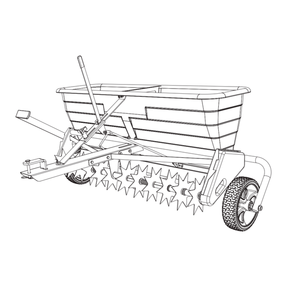
- Page 1 Want more information or assembly tips? Video Instruction Guide y o u t u b e . c o m / c / a g r i f a b 45-0545 175 LB. TOW SPIKER SPREADER PRINTED IN U.S.A. FORM NO. 45601 (01/17/19)
- Page 2 RULES FOR SAFE OPERATIONS Any power equipment can cause injury if operated improperly or if the user does not understand how to operate the equipment. Exercise caution at all times, when using power equipment. • Read this owner's manual before attempting to • Wear eye and hand protection when handling and assemble or operate the spiker/spreader. using lawn chemicals. • Read the towing vehicle owner's manual and know • Always begin with the transmission in first (low) gear how to operate the tractor before using the spiker/ and gradually increase speed as conditions permit. spreader. Maximum towing speed - 6 M.P.H. • Do not allow anyone to ride on or sit on the spiker/ • Do not drive too close to a creek or ditch and be alert spreader. for holes and other hazards which could cause you to lose control of the tractor and spiker/spreader. • Never allow children to operate the tractor or spiker/ spreader. • Before operating the vehicle on any grade (hill) refer to the safety rules in the vehicle owner's manual • Do not allow adults to operate the tractor or spiker/ concerning safe operation on slopes. Stay off steep spreader without proper instructions. slopes! • Read the chemical label for instructions and cautions • Follow maintenance and lubrication instructions as for handling and applying chemicals.
- Page 3 CARTON CONTENTS 11. Lift Tube Assembly 6. Flow Control Arm 1. Hopper Assembly 12. Axle 2. Chain Cover 7. Flow Control Rod 13. Drive Disk (2) 8. Tongue Braces (2) 3. Transport Handle 14. Spike Disk (10) 4. Hopper Brace 9. Tongue 15. Center Brace (2) 10. Hitch Bracket 5. Flow Control Gauge 16. Wheels (2) 24542 63850 47679 24647 47712 24660 23014 24532 24531 69441 63949 24648 28606 41863 69416...
- Page 4 SHOWN FULL SIZE 45100 43001 1509-90 (16) (24) 47189 1509-69 43866 HA21362 44950 43012 48106 44326 43082 (12) 47810 43019 (10) 48115 43088 R19171616 1543-69 R19212016 NOT SHOWN FULL SIZE 47684 43849 43093 47623 47707 43848 43343 (16) 47711 46838 741-0249 47782 47777...
- Page 5 ASSEMBLY 3. Press a flanged bearing (AA) into each end of both drive disks (13). See figure 2. TOOLS REQUIRED FOR ASSEMBLY (2) 7/16" Wrenches (2) 1/2" Wrenches (2) 9/16" Wrenches (2) 3/4" or Adjustable Wrenches (1) Pliers (1) Knife or Scissors Spike points are sharp. Wear protective gloves and exercise caution when working with hands near spike disks. FIGURE 2 1. Remove the hardware pack and all individual parts from 4. Press a flanged bearing (AA) into both center braces the carton and lay out as shown on pages 2 and 3. (15) from the flat side of each brace. See figure 3. 2. Press a flanged bearing (AA) into each spike disk (14) from the flat side of the disk. See figure 1. FIGURE 3 5. Assemble a 1/2" spacer (DD) and a 5/8" washer (O) FIGURE 1 onto the axle (12). See figure 4. FIGURE 4...
- Page 6 6. Assemble the axle (12) through the end of the spread- 8. Assemble two spike disks (14) and a 2.9" spacer (EE) er frame that contains a pre-assembled sprocket. See onto the axle. The flat side of the disks should face figure 5. away from the spacer. See figure 7. 9. Assemble two 5/8" washers (O) and a spring (BB) onto the axle. See figure 7. FIGURE 5 IMPORTANT: When assembling parts onto the axle, be sure that the spike disks are facing in the direction shown in each assembly drawing. 7. Assemble three 5/8" washers (O) and the two drive FIGURE 7 disks (13) onto the axle. See figure 6. 10. Assemble two spike disks (14) and a 2.9" spacer (EE) onto the axle. The flat side of the disks should face away from the spacer. See figure 8. FIGURE 6 FIGURE 8...
- Page 7 11. Assemble two 5/8" washers (O), the two center braces 14. Assemble two spike disks (14) and a 2.9" spacer (EE) (15) and the 3.2" spacer (FF) onto the axle. The flat onto the axle. The flat side of the disks should face side of the braces should face away from the spacer. away from the spacer. See figure 11. See figure 9. FIGURE 11 FIGURE 9 12. Assemble two spike disks (14) and a 2.9" spacer (EE) 15. Assemble 30" plastic ties around the each set of onto the axle. The flat side of the disks should face spike disks that surround the springs. Loop the ties away from the spacer. See figure 10. around opposite sides of each spike disk. Tighten the 13. Assemble two 5/8" washers (O) and a spring (BB) ties, compressing the springs so that there is room to onto the axle. See figure 10. assemble the rest of the parts onto the axle, and to insert the axle through the end of the spreader frame. See figure 12. 30" PLASTIC TIES FIGURE 10 FIGURE 12...
-
Page 8: Nylock Nut
16. Assemble a 2.9" spacer (EE) onto the axle. See figure 21. Assemble two cotter pins (V) into the drive disks (13). Spread the ends of the cotter pins. See figure 15. 17. Assemble two spike disks (14), a 2.9" spacer (EE) 22. Cut the plastic ties and remove them from the disks. and a 5/8" washer (O) onto the axle. The flat side See figure 15. of the disks should face away from the spacer. See figure 13. CAUTION: Spring tension is released when plastic ties are cut. Keep hands clear of spike disks to prevent injury. PLASTIC TIES FIGURE 15 23. Remove connecting link from chain and assemble the chain (T) around the sprockets, and then fasten the ends of the chain together using the connecting link. See figure 16. FIGURE 13 CONNECTING LINK 18. Slide the axle on through the end of the spreader frame. You may need to straighten the spike disks that are strapped together to allow the axle to slide freely. See figure 14. 19. Assemble a 5/8" washer (O) onto the end of the axle. See figure 14. 20. Assemble a cotter pin (V) into the end of the axle and then spread the ends of the cotter pin. See figure 14. HINT: You may need to push against the end plate to make room on the axle to install the cotter pin. Try turning the spreader on end to get better leverage for pushing. -
Page 9: Nylock Nut
25. Attach the lift tube assembly (11) to the spreader using the two shoulder bolts (I) and two 3/8" hex lock nuts (M). See figure 18. FIGURE 20 29. Assemble the plastic grip (Z) onto the end of the flow control arm (6). See figure 21. FIGURE 18 30. Insert the flow control arm (6) through the slot in the hopper brace (4). Place a nylon washer (R) on each side of the arm and attach it to the brace's welded bracket using a 1/4" x 1-1/4" hex bolt (C), a 1/4" flat 26 Assemble the end of the tongue (9) to the hopper using washer (Q), and two 1/4" nylock nuts (J). Tighten two 1/4" x 5/8" hex bolts (F) and 1/4" nylock nuts (J). the first nylock nut until there is noticeable resistance The holes are located just below the frame assembly when moving the flow control arm, then tighten the tube. Do not tighten yet. See figure 19. second nylock nut. See figure 21. 31. Place the flow control rod (7) through the hole at the end of the flow control arm (6). Assemble the two ferrules (CC) onto the threaded ends of the rod so that approximately 10 threads (1/2") of the rod extends through the ferrules. See figure 21. FRAME ASSEMBLY TUBE FIGURE 19 27. Attach the tongue to the frame assembly tube using a 1/4" x 1-3/4" hex bolt (D), two 1/4" flat washers (Q) and a 1/4" nylock nut (J). Repeat for the other side. Do not tighten yet. -
Page 10: Nylock Nut
32. Attach the hopper brace (4) to the hopper using two 1/4" x 5/8" hex bolts (F), one 1/4" flat washer (Q), and two 1/4" nylock nuts (J). Do not tighten yet. See figure 22. 33. Place the end of the hitch bracket (10) with two holes down through the slot in the tongue. Attach the hopper brace to the top of the tongue and the hitch bracket to the bottom using one 3/8" x 1" hex bolt (B) and one 3/8" nylock nut (L). Do not tighten yet. See figure 22. FIGURE 23 38. Assemble a 1/2" x 4" hex bolt (A), a 1/2" washer (P), a wheel, a 1/2" washer (P), and a 1/2" jam nut (N). Finger tighten only. Attach the wheel assembly to the transport tube using a 1/2" nylock hex jam nut (S). Repeat for the other side. See figure 24. FIGURE 22 FIGURE 24 34. Insert a tongue brace (8) through the slot in the end 39. Assemble the flow control gauge (5) to the hopper plate. Fasten the front hole of the tongue brace to the brace using the 1/4" x 3/4" carriage bolt (G), a nylon end plate using a 1/4" x 5/8" hex bolt (F) and 1/4" washer (R) and the plastic knob (X). See figure 25. nylock nut (J). For the rear hole use a 1/4" x 3/4" hex bolt (E), 1/4" flat washer (Q), and 1/4" nylock nut (J), with the bolt and washer assembled from inside the hopper. Do not tighten yet. See figure 23. 35. Fasten the other end of the tongue brace (8) to the side of the tongue using two 1/4" x 5/8" hex bolts (F) and 1/4" nylock nuts (J). Do not tighten yet. See... -
Page 11: Nylock Nut
40. Check that both ferrules (CC) are adjusted so that 43. Attach the transport handle (3) to the lift assembly arm approximately ten threads (1/2") of the control rod is using the two pre-assembled 5/16" x 1" carriage bolts exposed. Insert both ferrules into the brackets which and 5/16" nylock nuts (K). See figure 27. are riveted to the front of the flow plates. Assemble 44. Assemble the handle grip (Y) to the transport handle a 1/4" nylock nut (J) onto each ferrule, making only (3). See figure 27. finger tight at this time. See figure 26. BRACKET FIGURE 26 FIGURE 27 45. Assemble the chain cover (2) to the frame assembly using two 1/4" x 5/8" hex bolts (F), 1/4" flat washers (Q) and 1/4" nylock nuts (J) as shown figure 28. 41. To check for correct opening of hopper flow plates: Please note that some parts are not shown for clarity. a. Set the flow control gauge at the highest setting. 46. Install the hitch pin (U) and the 1/8" hair cotter pin (W) b. Move the flow control arm away from the hopper in the spreader hitch bracket and tongue. until it rests against the gauge. The slots in the See figure 28. bottom of the hopper should now be completely open. The edge of the flow plates should be just clear of the ends all the slots. c. If the flow plates are not straight with the slots, screw one ferrule up or down on one side of the control rod. d. If the flow plates open to far or not far enough, screw both ferrules equally up or down on the control rod. - Page 12 OPERATION SETTING CHART HOW TO USE YOUR SPIKER/SPREADER Flow Rate Setting 1. Refer to the instruction label on the material package MATERIAL TYPE At 3 M.P.H. and to the instruction decal on your spreader to help Fertilizer Granular / Pelleted 0-1 / 0-2 determine the proper spreader setting and application rate. Also see the Setting Chart on this page for Grass Seed Fine / Coarse 5-6 / 7-8 a general range of settings for commonly used materials. 3 M.P.H. is equivalent to traveling 100 feet in 23 seconds. 2. Loosen the knob and adjust the flow control gauge to the recommended setting. Retighten the knob. See APPLICATION TIPS figure 29. 1. To help prevent compacting and clogging when using 3. Determine the approximate square footage of the area granular material, avoid unnecessary towing while...
- Page 13 PARTS FOR 175 LB. POLY "PRO" SPIKER/SPREADER MODEL 45-0545 SEE PARTS DIAGRAM ON PAGE 14 PART NO. QTY DESCRIPTION PART NO. QTY DESCRIPTION 43848 Plastic Grip 47623 Pin, Hitch 3/8" Flat Hd. 24660 Flow Control Arm 23014 Hitch Bracket 47712 Flow Control Rod 24531 Tongue 47711 Ferrule 43343 Pin, Hair Cotter #4 (1/8") 1543-69...
- Page 14 PARTS FOR 175 LB. TOW SPIKER SPREADER MODEL 45-0545...
- Page 15 PARTS FOR 175 LB. TOW SPIKER SPREADER MODEL 45-0545 PART NO. QTY DESCRIPTION PART NO. QTY DESCRIPTION 47451 Hopper 26007 Step Bushing (Special) 24536 Hopper Center Plate (Small) 69441 Lift Tube Assembly 24535 Hopper Center Plate (Large) 741-0249 Bearing, Flanged 0.63" I.D. 43088 Washer, 1/4" 47684 Chain with Connector 43866 Bolt, Hex 1/4-20 x 5/8" 48106 Bolt, Shoulder 3/8-16 x 5/8" 46978 Nut, Hex (SIMS) 1/4-20 Thd. 43082...
- Page 16 REPAIR PARTS Agri-Fab, Inc. 809 South Hamilton Sullivan, IL. 61951 217-728-8388 www.agri-fab.com This document (or manual) is protected under the U.S. Copyright Laws and the copyright laws of foreign countries, pursuant to the Universal Copyright Convention and the Berne convention. No part of this document may be reproduced or transmitted in any form or by an means, electronic or mechanical, including photocopying or recording, or by any information storage or retrieval system, without the express written permission of Agri-Fab, Inc. Unauthorized uses and/or reproductions of this manual will subject such unauthorized user to civil and criminal penalties as provided by the United States Copyright Laws. © 2000 Agri-Fab, Inc.
Need help?
Do you have a question about the 45-0545 and is the answer not in the manual?
Questions and answers