Table of Contents
Advertisement
Advertisement
Table of Contents
Troubleshooting

Related Manuals for Alnor AirGard 335


Summary of Contents for Alnor AirGard 335
- Page 1 OWNER’S MANUAL ® AirGard Fume Hood Monitor...
- Page 2 Seller Service Policy Knowing that inoperative or defective instruments are as detrimental to Alnor as they are to our customers, our service policy is designed to give prompt attention to any problems. If any malfunction is discovered, please contact your nearest sales office or representative, or call Alnor’s Customer Service department at (800) 424-7427 (USA) and (1) 651-490-2811...
-
Page 3: Table Of Contents
TABLE OF CONTENTS Section 1 Introduction General Description ............3 Component Identification ..........4 Section 2 Installation Tools Required ............. 7 Mounting the Monitor ..........7 Electrical Wiring............8 Section 3 Calibration Overview ..............10 Low Alarm Setup ............14 Section 4 Normal Operation Power Up Sequence............ - Page 4 Section 6 Troubleshooting and Service Error Codes..............38 Troubleshooting Guide ..........39 Service Requests............40 Section 7 Mounting Template............41...
-
Page 5: General Description
SECTION 1 Introduction General Description Air is drawn into a fume hood by an exhaust system that produces a differential pressure between the interior of the fume hood and the surrounding laboratory. The average velocity of the air moving perpendicular through the front sash opening of the hood is called the face velocity. -
Page 6: Component Identification
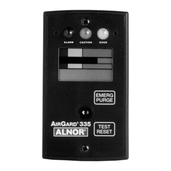
Component Identification Status LEDs Mounting (red, yellow and green) Screw Down Button Up Button Colored Bands Analog Bargraph Digital Display Emergency Purge Button Air Inlet Test/Reset Button Mounting Screw Figure 1 — Front View of Instrument... - Page 7 Status LEDs Red (Alarm) — Indicates a high or low airflow alarm; Yellow (Caution) — Indicates that the airflow is within the caution zone between normal and low alarm; Green (Good) — Indicates that the airflow is within normal range. Up Button Up scroll button for configuration and calibration.
- Page 8 Terminal Block Communications Port Power Jack Flow Tube Figure 2—Back View of Instrument Communications Port For factory use only. Flow Tube Connects the flexible air hose attached to the fume hood side wall. Terminal Block Accepts 14-24 AWG wires. See the Installation section for wiring the monitor’s various input/output features.
-
Page 9: Installation
SECTION 2 Installation Tools Required 1. Power Drill 2. Drill bit size #37 (0.104 inch) (2.6 mm) 3. 9/16 inch (14 mm) diameter hole saw for cutting into side wall 4. Reciprocating saw with saw blades for cutting sheet metal 5. -
Page 10: Electrical Wiring
5. Drill one 9/16 inch (14 mm) diameter hole in the size wall of the fume hood approximately 6 inches (152 mm) behind the sash and 1 inch (25.4 mm) above the sash bottom when it is at its true fully open position. - Page 11 ALRM INPUT (Alarm Input): This allows you to remotely activate the Test/Reset or Emergency Purge functions via a contact closure or wire an external alarm/event into the monitor. The external alarm function may be wired to use open or closed contacts. When wired for “open” contacts, opening the contacts will activate the monitor’s alarm;...
-
Page 12: Calibration
SECTION 3 Calibration Overview IMPORTANT: Calibration procedures are for a constant volume hood. If you have a VAV hood, call TSI for the calibration procedure. The fume hood monitor must be calibrated before first use and checked annually thereafter. The calibration is stored in the non-volatile memory of the instrument and is not lost when the monitor loses power. - Page 13 an appropriate live electrical outlet. The monitor must be warmed up for at least 10 minutes to reach a stable operating temperature. NOTE: For the two point calibration, high and low face velocities need to be determined. These two values must be between 50 and 250 fpm (0.25 and 1.27 m/s).
- Page 14 NOTE: If an error message is displayed at this point, there is problem with the calibration and the procedure will be terminated. See Calibration Error Codes below. 8. Move the sash to the 12 inch (305 mm) open position (the point where the high flow face velocity traverse was conducted).
- Page 15 If a calibration error is detected, the user must press the Test/Reset button to acknowledge the error condition. After acknowledgement, the monitor will return to the CAL configuration menu selection so that another calibration can be attempted. The incorrect values will not be stored in memory.
-
Page 16: Low Alarm Setup
Low Alarm Setup The low alarm setpoint should be established before first use and checked annually thereafter. The alarm setup is stored to nonvolatile memory and is not lost when the monitor loses power. Procedure 1. Verify that the monitor was properly installed. 2. -
Page 17: Normal Operation
SECTION 4 Normal Operation Power Up Sequence On power up, the digital display is initialized and every segment of the display turned on for two seconds. All three of the LEDs and the horn are also activated. After the two seconds has expired, the three LEDs and the horn will turn off. -
Page 18: Monitor Test
Monitor Test During normal operation, pressing and holding the Test/Reset Button for 2 to 5 seconds will turn on all segments on the LCD and all LEDs as well as the horn and the alarm relay output. To test the emergency purge feature, press the Emergency Purge button;... -
Page 19: Viewing Alarm Set Points
Temporary Horn Disable Pressing the Test/Reset button temporarily silences the horn. The horn slash through icon will be on the display indicating that the horn is temporarily disabled. If the horn is temporarily disabled, it will turn off and not come back on until either the temporary horn disable timer expires or until the monitor detects another alarm condition. -
Page 20: High Alarm Disable
The displayed setting is changed by pressing the Up and Down Buttons. The Up Button will increment the set point by 1 fpm or by 0.01 m/s, depending on the units configuration. The Down Button will decrement the set point by 1 fpm or by 0.01 m/s. When the desired setting is displayed, press the Test/Reset Button. -
Page 21: Section 5 Parameter Configuration
SECTION 5 Parameter Configuration General NOTE: Configurable parameters are stored to nonvolatile memory of the instrument and will not be lost when the monitor loses power. To access the Configuration mode, press and hold the Test/Reset button until you hear a double beep and see CAL displayed. NOTE: This Calibration initialization sequence takes approximately 10 seconds, during which the display will be fully lit (all segments on) for about 3 seconds and then blank (all segments off) for about 5... -
Page 22: Configuration Parameters
Configuration menu after 1 minute has elapsed without any keypad activity. SUMMARY: Pressing the Test/Reset button for 10 seconds accesses the Configuration menu. Pressing the Up or Down Button advances to the next parameter and also navigates within a selection. Pressing once manually scrolls;... -
Page 23: Cal - Calibration
CAL — Calibration See Section 3 Calibration. P01 — Digits Enabled/Disabled The digits can be enabled or disabled using this Configuration Parameter. It only disables the numeric airflow velocity reading. The status indicators and icons will not be turned off. After this Configuration menu selection is entered, the monitor will turn on the program mode PGM descriptor and, if the digits are disabled, will show:... -
Page 24: P03 - Temporary Horn Disable Timer
After this Configuration menu selection is entered, the monitor will turn on the program mode PGM descriptor and display the current unit descriptor: Press the Up or Down Button to toggle between the two settings. When the desired setting is displayed, press the Test/Reset button. The PGM descriptor will flash once and the horn will give two quick beeps to acknowledge the save. -
Page 25: P04 - Caution-To-Alarm Transition Delay Timer
Press the Up Button to increase the timer value by 1 minute or the Down Button to decrease the timer value by 1 minute. When the desired setting is displayed, press the Test/Reset button. The PGM descriptor will flash once and the horn will give two quick beeps to acknowledge the save. -
Page 26: P05 - Alarm-To-Caution Transition Delay Timer
The monitor will return to the P04 Configuration menu selection. Press the Up and Down Buttons to advance to another Configuration Parameter. Press and hold the hold the Test/Reset button for 2 seconds to exit the Configuration menu. P05 — Alarm-to-Caution Transition Delay Timer The red alarm to yellow caution transition time is the delay period in seconds that an air flow condition must remain present before the monitor will go into the appropriate warning zone. -
Page 27: P06 - Low Alarm Caution Offset
P06 — Low Alarm Caution Offset The low caution offset defines the starting point of the low caution zone. It is a value (in the current unit of measure) that is added to the low alarm set point. It determines when the yellow low caution light comes on. -
Page 28: P07 - Dis Input
P07 — Dis Input This Configuration Parameter configures the switch settings for the instrument’s Remote Test/Reset , Remote Emergency Purge, and Night Setback features. After this Configuration menu selection is entered, the monitor will turn on the Program mode PGM descriptor and display the current setting. - Page 29 Night Setback — Night setback can be configured for either a contact closure or opening. If the monitor is configured to go into the night setback mode when the contacts are closed, the display will show: If the monitor is configured to go into night setback when the contacts are opened, the display will show: When activated, the nigh setback performs one of two possible actions, based on the setting of P12.
-
Page 30: P08 - Alarm Input
low alarm setting, but does not allow you to turn it off. See P12 for information on turning the night setback low alarm off. When the desired setting (Remote Test/Reset, Remote Emergency Purge, or Night Setback) is displayed, press the Test/Reset button. The PGM descriptor will flash once and the horn will emit two quick beeps to acknowledge that the setting has been saved. - Page 31 Sash Override/External Alarm Input — A selection can be made between a sash override input and external alarm input. The differences between the inputs relates to the visual, audible, and remote indications activated when the input is received by the monitor. The sash override input can be connected to a sash position switch on the fume hood to indicate that the sash has exceeded a given height and a full alarm is sounded.
-
Page 32: P09 - Relay Output 1
If the monitor is configured for open contacts to activate the external alarm, the display will show: If the monitor is configured for closed contacts to activate the sash override alarm, the display will show: If the monitor is configured for open contacts to activate the sash override alarm, the display will show: Press either the Up or Down button to scroll through the settings. - Page 33 Relay Function Setting Displayed Contact State Not Used --.1 Always open Alarm Output CL.1 with horn icon Closed when in and red LED alarm Alarm Output OP.1 with horn icon Open when in alarm and red LED or when power is lost Caution Output CL.1 with horn icon...
- Page 34 The relay function is disabled when the display shown above is selected. The relay function is enabled when one of the following displays is selected. NOTE: The red LED at the top of the instrument will light in conjunction with two displays shown above when the Alarm Output selections appear;...
-
Page 35: P10 - Relay Output 2
Press either the Up or Down button to cycle through the settings. When the desired setting is displayed, press the Test/Reset button. The PGM descriptor will flash once and the horn will give two quick beeps to acknowledge the save. The monitor will return to the P09 Configuration menu selection. - Page 36 The relay function is disabled when the display shown above is selected. The relay function is enabled when one of the following displays is selected. NOTE: The red LED at the top of the instrument will light in conjunction with two displays above when the Alarm Output selections appear;...
-
Page 37: P11 - High Alarm Relay Disable
Press either the Up or Down button to cycle through the settings. When the desired configuration is displayed, press the Test/Reset button. The PGM descriptor will flash once and the horn will give two quick beeps to acknowledge the save. The monitor will return to the P10 Configuration menu selection. -
Page 38: P12 - Night Setback Low Alarm
Parameter. Press and hold the hold the Test/Reset button for 2 seconds to exit the Configuration menu. P12 — Night Setback Low Alarm This Configuration Parameter sets the night setback low alarm. After this configuration menu selection is entered, the monitor will turn on the program mode PGM descriptor and display the current value for the night setback low alarm. -
Page 39: Def - Reset Configuration Parameters To Factory Default Settings
dEF — Reset Configuration Parameters to Factory Default Settings PO1 – PO11 can be reset to the factory defaults located in the memory of the fume hood monitor. This does not reset the field calibration or the low and high alarm settings. After this configuration menu selection is entered, the monitor will turn on the program mode PGM descriptor and the display will show: Press the Test/Reset button. -
Page 40: Section 6 Troubleshooting And Service
SECTION 6 Troubleshooting and Service Error Codes NOTE: Error codes associated with Calibration (ErL, ErH, Err, and Er2 do not affect normal operation. See Section 2: Installation for more information on Calibration Error Codes. Error checks are continuously performed on the monitor. In the event the monitor detects an error, an error message will continuously flash on the display to alert the user. -
Page 41: Troubleshooting Guide
Troubleshooting Guide Possible Cause / Problem Corrective Action No display or lights. The power supply cord is not plugged into the monitor or live AC outlet. No audible alarm when Audible alarm disabled. If horn slash display shows Lo or Hi. through icon is flashing, the horn has been permanently disabled. -
Page 42: Service Requests
Parameters P04 and P05 to set the transition delays. Service Requests If you need assistance, please contact TSI. Ship to: TSI Incorporated Alnor Products 500 Cardigan Road Shoreview, MN 55126 USA Toll-Free (800) 424-7427 Telephone (651) 490-2811 Fax (651) 490-3824 Email: customerservice@Alnor.com... -
Page 43: Section 7 Mounting Template
SECTION 7 Mounting Template Mounting Holes #6-20 Screws... - Page 45 ® AIRGARD 335 MONITOR SPECIFICATIONS Digital Display 3 digit, 7 segment LCD with status indicators and icons. Electronic bargraph moves through colored zones as the velocity changes. Display Units If digits are enabled, velocity is represented in feet per minute (fpm) or meters per second (m/s). User selectable through menu.
- Page 46 TSI Incorporated Alnor Products 500 Cardigan Road Shoreview, MN 55126 USA Toll-Free (800) 424-7427 February 2003 Telephone (651) 490-2811 Printed in USA Fax (651) 490-3824 Patent #4,982,605 Email: customerservice@Alnor.com Part No. 116-159-255 Rev. 5 www.alnor.com © Copyright 2003 TSI Incorporated...
Need help?
Do you have a question about the AirGard 335 and is the answer not in the manual?
Questions and answers