Advertisement
Quick Links
Advertisement

Related Manuals for Alnor AIRGARD 335-D

Summary of Contents for Alnor AIRGARD 335-D
- Page 1 FUME HOOD MONITOR ALNOR AIRGARD ® ® OWNER’S MANUAL P/N 116159255, REV 11 MARCH 2022...
- Page 3 LIMITATION OF WARRANTY AND LIABILITY (effective April 2014) (For country-specific terms and conditions outside of the USA, please visit www.tsi.com.) Seller warrants the goods, excluding software, sold hereunder, under normal use and service as described in the operator's manual, to be free from defects in workmanship and material for 24 months, or if less, the length of time specified in the operator's manual, from the date of shipment to the customer.
- Page 4 TSI’s Customer Service department at 1-800-680-1220 (USA) or (651) 490-2860. Trademarks TSI, Alnor, AirGard, and the TSI logo are registered trademarks of TSI Incorporated in the United States and may be protected under other country’s trademark registrations.
- Page 5 TABLE OF CONTENTS SECTION 1 Introduction ............3 General Description ..............3 Component Identification ............4 SECTION 2 Installation .............. 7 Tools Required ................. 7 Mounting the Monitor ............... 7 Electrical Wiring ............... 8 SECTION 3 Calibration ............11 Overview ................11 Tools Required ..............
- Page 6 P08 — Alarm Input ............. 34 P09 — Relay Output 1 ............37 P10 — Relay Output 2 ............39 P11 — High Alarm Relay Disable ........41 P12 — Night Setback Low Alarm ........42 dEF — Reset Configuration Parameters to Factory Default Settings ...............
- Page 7 SECTION 1 Introduction General Description Air is drawn into a fume hood by an exhaust system that produces a differential pressure between the interior of the fume hood and the surrounding laboratory. The average velocity of the air moving perpendicular through the front sash opening of the hood is called the face velocity.
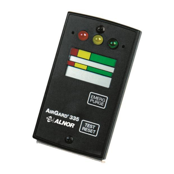
- Page 8 Component Identification Status LEDs Mounting (red, yellow and green) Screw Down Button Up Button Colored Bands Analog Bar graph Digital Display Emergency Purge Button Air Inlet Test/Reset Button Mounting Screw Figure 1 — Front View of Instrument...
- Page 9 Red (Alarm) — Indicates a high or Status LEDs low airflow alarm; Yellow (Caution) — Indicates that the airflow is within the caution zone between normal and low alarm; Green (Good) — Indicates that the airflow is within normal range. Up Button Up scroll button for configuration and calibration.
- Page 10 Terminal Block Communications Port Power Jack Flow Tube Figure 2—Back View of Instrument Communications Port For factory use only. Flow Tube Connects the flexible air hose attached to the fume hood side wall. Terminal Block Accepts 14-24 AWG wires. See the Installation section for wiring the monitor’s various input/output features.
- Page 11 SECTION 2 Installation Tools Required 1. Power drill 2. Drill bit size #37 (0.104 inch) (2.6 mm) 3. 9/16 inch (14 mm) diameter hole saw for cutting into side wall 4. Reciprocating saw with saw blades for cutting sheet metal 5.
- Page 12 portion of the monitor. Mark off the two mounting screw hole locations. 3. Drill a pilot hole in each of the four corners. Use the saw to cut out the hole. A suitable nibbling tool may also be used. 4. Drill the two #37 (0.104 inch) (2.6 mm) mounting screw holes.
- Page 13 for input/output features. See the Configuration Parameters section where indicated. The connections available are described below: DIS INPUT: This allows you to activate the Test/Reset or Emergency Purge functions with a remote contact closure or remotely disable the monitor or change to a lower alarm setpoint during night setback.
- Page 14 Figure 3 – Field Wiring Diagram...
- Page 15 Performance of Laboratory Fume Hoods, section 6.2 Face Velocity Measurements. Tools Required 1. Calibrated thermo-anemometer. Suggested instruments ® include the Alnor Model 9870D or Model CF8570. 2. Small pointed tool to press the recessed Up and Down buttons. A straightened paper clip works well. Procedure 1.
- Page 16 2. The power supply plug should be firmly in the power jack on the back of the monitor and the power supply should be plugged into an appropriate live electrical outlet. The monitor must be warmed up for at least 10 minutes to reach a stable operating temperature.
- Page 17 4. Press the Test/Reset button to begin the calibration process. Lo will be displayed for two seconds and then the low calibration reference starting point. Use the Up or Down buttons to adjust the displayed value to match the actual measured low face velocity (sash full open).
- Page 18 the Up/Down buttons. To exit and return to the Run mode, press and hold the Test/Reset button for two seconds. Variable Air Volume (VAV) Laboratory Fume Hoods Changing the sash position on a VAV system will not change the average face velocity thru the hood. In order to calibrate the 335 installed on a VAV fume hood, it will be necessary to change the average face velocity thru the hood to generate a low and high velocity calibration set point.
- Page 19 VAV fume hood with sash full open VAV fume hood with sash full open with half blocked off Variable Air Volume (VAV) Laboratory Fume Hood Calibration Once the methodology for establishing a low and high face velocity on a VAV fume hood has been determined, proceed with the following steps to calibrate the 335 fume hood monitor.
- Page 20 N O T I C E If an error message is displayed at this point, there is problem with the calibration and the procedure will be terminated. See Calibration Error Codes below. 4. Adjust the VAV system to the point where the high flow face velocity traverse was conducted.
- Page 21 Error Code Cause Airflow below the instrument’s measurement range. Airflow above the instrument’s measurement range. Too much variation in airflow. Insufficient difference between the low and high calibration points. If a calibration error is detected, the user must press the Test/Reset button to acknowledge the error condition.
- Page 22 ▪ Make sure the hose is connected properly to the sidewall of the hood and the monitor and is not kinked. ▪ Check for presence of a diffuser or supply grille right above, or close to, the hood. If air is being “pushed” toward the front of the monitor, try diverting or blocking it.
- Page 23 SECTION 4 Normal Operation Power Up Sequence On power up, the digital display is initialized and every segment of the display turned on for two seconds. All three of the LEDs and the horn are also activated. After the two seconds has expired, the three LEDs and the horn will turn off.
- Page 24 Monitor Test During normal operation, pressing and holding the Test/Reset Button for 2 to 5 seconds will turn on all segments on the LCD and all LEDs as well as the horn and the alarm relay output. To test the emergency purge feature, press the Emergency Purge button;...
- Page 25 Temporary Horn Disable Pressing the Test/Reset button temporarily silences the horn. The horn slash through icon will be on the display indicating that the horn is temporarily disabled. If the horn is temporarily disabled, it will turn off and not come back on until either the temporary horn disable timer expires or until the monitor detects another alarm condition.
- Page 26 reading and the selected set point. If the button is held for five seconds, the monitor goes into a program mode that allows changing the selected set point. The corresponding LED will continuously flash and the display will turn on the PGM descriptor to indicate that the monitor is in program mode.
- Page 27 Emergency Purge This button can be configured to activate a relay that can be used to command the fume hood damper to full open until pressed again. See Configuration Parameter set up the relay.
- Page 28 (This page intentionally left blank)
- Page 29 SECTION 5 Parameter Configuration General N O T I C E Configurable parameters are stored to nonvolatile memory of the instrument and will not be lost when the monitor loses power. To access the Configuration mode, press and hold the Test/Reset button until you hear a double beep and see CAL displayed.
- Page 30 I M P O R T A N T N O T I C E If the Test/Reset button is pressed and held for 2 seconds, the change will not be saved; this is signalled via one long horn beep. All parameters are configured in the same manner.
- Page 31 Configuration Parameter Factory Default P09 — Relay output 1 CL.1 (alarm output, contacts close with alarm) P10 — Relay output 2 OP.2 (alarm output, contacts open in alarm) P11 — High alarm relay P12 — Night setback low alarm dEF — Default reset Resets P01 –...
- Page 32 The monitor will return to the P01 Configuration menu selection. Press the Up and Down Buttons to advance to another Configuration Parameter. Press and hold the hold the Test/Reset button for 2 seconds to exit the Configuration menu. P02 — Unit of Measure The velocity can be displayed either in feet per minute (fpm) or in meters per second (m/s), with the applicable descriptor (fpm or m/s) on during normal run mode.
- Page 33 when the alarm is temporarily silenced by pressing the Test/Reset button, the horn will not come on again until this alarm condition clears and another alarm event occurs. A setting of 0 is used to prevent silencing of the horn by pressing the Test/Reset button.
- Page 34 For example, if the monitor is currently configured for a caution- to-alarm transition time of three seconds, the display will show: Press the Up Button to increase the timer value by 1 second or the Down Button to decrease the timer value by 1 second. When the desired setting is displayed, press the Test/Reset button.
- Page 35 the desired setting is displayed, press the Test/Reset button. The PGM descriptor will flash once and the horn will give two quick beeps to acknowledge the save. The monitor will return to the P05 Configuration menu selection. Press the Up and Down Buttons to advance to another Configuration Parameter.
- Page 36 P07 — Dis Input This Configuration Parameter configures the switch settings for the instrument’s Remote Test/Reset, Remote Emergency Purge, and Night Setback features. After this Configuration menu selection is entered, the monitor will turn on the Program mode PGM descriptor and display the current setting. Press the Up and Down arrow keys to scroll through the available settings.
- Page 37 Night Setback — Night setback can be configured for either a contact closure or opening. If the monitor is configured to go into the night setback mode when the contacts are closed, the display will show: If the monitor is configured to go into night setback when the contacts are opened, the display will show: When activated, the nigh setback performs one of two possible actions, based on the setting of P12.
- Page 38 low alarm setting, but does not allow you to turn it off. See for information on turning the night setback low alarm off. When the desired setting (Remote Test/Reset, Remote Emergency Purge, or Night Setback) is displayed, press the Test/Reset button. The PGM descriptor will flash once and the horn will emit two quick beeps to acknowledge that the setting has been saved.
- Page 39 Emergency Purge button on the instrument’s front panel (see Section 1). The local Emergency Purge button is still active even if the instrument is configured for Remote Emergency Purge. If this function is active, the following display will appear under P08: Sash Override/External Alarm Input —...
- Page 40 If the monitor is configured for closed contacts to activate the external alarm, the display will show: If the monitor is configured for open contacts to activate the external alarm, the display will show: If the monitor is configured for closed contacts to activate the sash override alarm, the display will show: If the monitor is configured for open contacts to activate the sash override alarm, the display will show:...
- Page 41 The monitor will return to the P08 Configuration menu selection. Press the Up and Down Buttons to advance to another Configuration Parameter. Press and hold the hold the Test/Reset button for 2 seconds to exit the Configuration menu. P09 — Relay Output 1 This relay output has contacts that are open in the non- energized state.
- Page 42 The relay function is disabled when the display shown above is selected. The relay function is enabled when one of the following displays is selected. N O T I C E The red LED at the top of the instrument will light in conjunction with two displays shown above when the Alarm Output selections appear;...
- Page 43 The monitor will return to the P09 Configuration menu selection. Press the Up and Down Buttons to advance to another Configuration Parameter. Press and hold the hold the Test/Reset button for 2 seconds to exit the Configuration menu. P10 — Relay Output 2 This relay output has contacts that are closed in the non- energized state.
- Page 44 The relay function is disabled when the display shown above is selected. The relay function is enabled when one of the following displays is selected. N O T I C E The red LED at the top of the instrument will light in conjunction with two displays above when the Alarm Output selections appear;...
- Page 45 The monitor will return to the P10 Configuration menu selection. Press the Up and Down Buttons to advance to another Configuration Parameter. Press and hold the hold the Test/Reset button for 2 seconds to exit the Configuration menu. P11 — High Alarm Relay Disable The alarm state can be sent to a remote location by means of a relay output.
- Page 46 P12 — Night Setback Low Alarm This Configuration Parameter sets the night setback low alarm. After this configuration menu selection is entered, the monitor will turn on the program mode PGM descriptor and display the current value for the night setback low alarm. It may be set to “OFF”...
- Page 47 Press the Test/Reset button. The PGM descriptor will be continuously displayed and the horn will give two quick beeps to acknowledge that the configuration settings have been set to their factory default settings. The monitor will return to the dEF Configuration menu selection. Press the Up and Down Buttons to advance to another Configuration Parameter.
- Page 48 (This page intentionally left blank)
- Page 49 SECTION 6 Troubleshooting and Service Error Codes N O T I C E Error codes associated with Calibration (ErL, ErH, Err, and Er2 do not affect normal operation. See Section 2: Installation more information on Calibration Error Codes. Error checks are continuously performed on the monitor. In the event the monitor detects an error, an error message will continuously flash on the display to alert the user.
- Page 50 Possible Cause / Problem Corrective Action Pulsed audible alarm. This indicates an external alarm. The EXT descriptor on the LCD should also be on. Attend to the external alarm event. See Configuration Parameter P08. Nothing happens when the The emergency purge function is not Emergency Purge button is configured.
- Page 51 Service Requests ® If you need assistance, please contact TSI Incorporated. Ship to: TSI Incorporated Alnor Products 500 Cardigan Road Shoreview, MN 55126 USA Toll-Free (800) 680-1220 Telephone (651) 490-2860 Fax (651) 490-3824 Email: technical.services@tsi.com tsi.com/service...
- Page 52 (This page intentionally left blank)
- Page 53 SECTION 7 Mounting Template Mounting Holes #6-20 Screws...
- Page 55 ® AIRGARD 335 MONITOR SPECIFICATIONS Digital Display 3 digit, 7 segment LCD with status indicators and icons. Electronic bargraph moves through colored zones as the velocity changes. Display Units If digits are enabled, velocity is represented in feet per minute (fpm) or meters per second (m/s). User selectable through menu.
- Page 56 Alnor Products, TSI Incorporated Visit our website www.tsi.com for more information. Tel: +1 800 680-1220 China Tel: +86 10 8219 7688 India Tel: +91 80 67877200 Singapore Tel: +65 6595 6388 P/N 116159255 Rev 11 ©2022 TSI Incorporated Printed in U.S.A.
Need help?
Do you have a question about the AIRGARD 335-D and is the answer not in the manual?
Questions and answers