
Subscribe to Our Youtube Channel
Related Manuals for CLIMAVENETA BRA2 0021


Summary of Contents for CLIMAVENETA BRA2 0021
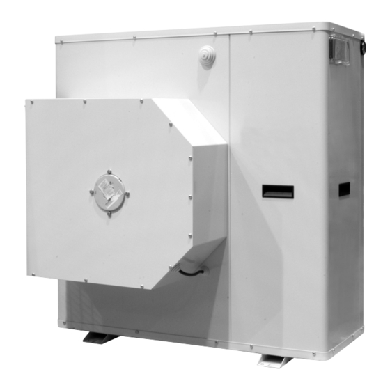
- Page 1 INSTALLATION, USER AND MAINTENANCE MANUAL Water chillers and air/water heat pumps with centrifugal fans BRA2 0021÷0061 BRN2 0021÷0061...
- Page 2 INDEX U I A General warnings Pressure drop and pressure head available to system U I A Waiver of liability Fan pressure gain curves U I A Fundamental safety rules Checking and starting up the unit Identification Led e displays Receiving, handling and installing the product Displaying alarms...
-
Page 3: General Warnings
“start-up” report. WAIVER OF LIABILITY U I A This publication is the sole property of Climaveneta. Any All work must be performed, components selected and reproduction or disclosure of such is strictly prohibited with- materials used professionally and in complete accordance out the written authorisation of Climaveneta. -
Page 4: Choice Of Installation Site
IDENTIFICATION U I A The chiller can be identified by the: Packaging label De' Longhi S.p.a. - 31100 Treviso / Italia Via L.Seitz, 47 - tel. 04224131 fax 0422413659 Giving the data identifying the product. MODEL: VOLTAGE: CODE: Rating plate Giving the technical and performance data of the unit. - Page 5 BAR CODE Hole Ø22 BRA2 Dimensions and weight with standard packaging Size 0021M-T 0025M-T 0031M-T 0041M-T 0051T 0061T Dimension Dimension 1140 1140 1440 1440 1590 Dimension Weight BRN2 Dimensions and weight with standard packaging Size 0021M-T 0025M-T 0031M-T 0041M-T 0051T 0061T Dimension Dimension...
-
Page 6: Disegni Dimensionali
The connection piping should be supported in such Climaveneta cannot be held liable for any damage to the a way as to avoid it weighing on the unit. It is recommended... - Page 7 Minimum system water content Size 0021M-T 0025M-T 0031M-T 0041M-T 0051T 0061T Minimum water content BRA2 Minimum water content BRN2 Expansion vessel size Size 0021M-T 0025M-T 0031M-T 0041M-T 0051T 0061T Expansion vessel BRA2 Expansion vessel BRN2 Safety valve calibration Size 0021M-T 0025M-T 0031M-T 0041M-T...
-
Page 8: Installer Connections
System water circuit connection diagram, BRN2 version WITH HYDRONIC KIT FACTORY CONNECTED INSTALLER CONNECTIONS PRESSURE GAUGE UTILITY VIBRATION-ISOLATING JOINT OUTLET SHUT-OFF VALVE CALIBRATING VALVE FLOW SWITCH THERMOMETER CIRCULATOR PUMP SAFETY VALVE EXPANSION VESSEL 10 MESH FILTER 11 FILL/TOP-UP 12 TEMPERATURE PROBE 13 DIFFERENTIAL PRESSURE SWITCH 14 DRAIN/CHEMICAL WASHING... - Page 9 Fouling factors Evaporator Fouling factors °C/W) The performance data given refer to conditions with clean evaporator plates (fouling factor = 1). 4,4 x 10 For different fouling factors, multiply the figures in the perfor- 0,86 x 10 0,96 0,99 0,99 mance tables by the coefficient given in the following table.
-
Page 10: Filling The System
FILLING THE SYSTEM - Before filling, check that the system drain valve is closed. The system must be filled to a pressure of between 1 - Open all system and terminal air vents. and 2 bars. - Open system shut off valves. It is recommended that this operation be repeated after - Start filling by slowly opening the system water fill cock the unit has been operating for a number of hours. -
Page 11: Air Ducting
AIR DUCTING The BRA2-BRN2 models are designed for indoor and out- door installation. The cooling air outlet can be ducted to the outside Ducting the air outlet The air outlet ducting connection has the following charac- teristics. Model 0061 Model 0041 - 0051 Model 0025 - 0031 Model 0021 BRA2 - BRN2... - Page 12 The appliance is factory fitted with the air outlet in position A (side). To move it to position B (top) for model 0021. - Undo the fastening screws and remove the fan holder cov- er P on the air outlet collar. - Unscrew the four fastening bolts and remove the air outlet collar.
-
Page 13: Electrical Connections
ELECTRICAL CONNECTIONS The BRA2 and BRN2 units leave the factory already wired, Voltage must be within a tolerance of ±10% of the rated and require the installation of an omnipolar thermal overload power supply voltage for the unit (for three phase units, switch, a lockable mains disconnecting switch for the con- the unbalance between the phases must not exceed nection to the mains power supply, and the connection of... - Page 14 MAINS POWER SUPPLY CONNECTIONS • Before connecting the unit to the power supply, makes • Use cable gland A for the main electrical power cable and sure that switch QF1 is open, suitably padlocked and cable gland B for other external cables to be connected by marked.
-
Page 15: Technical Data
OUTSIDE AIR PROBE (BT3) (Accessory) The outside air probe allows the system water temperature set point to be compensated during heating or cooling opera- tion. Installation instructions The outside air probe must be installed: • outside of the home • not in direct sunlight, away from flue gas discharges, air outlets, or doors and windows. -
Page 16: General Technical Data
GENERAL TECHNICAL DATA BRA2 without hydronic kit 0021 0025 0031 0041 0021 0025 0031 0041 0051 0061 Cooling capacity [kW] 7,71 9,50 11,5 15,0 7,70 11,60 15,7 17,9 20,5 Power consumption [kW] 2,29 2,79 3,80 4,60 2,22 2,59 3,55 4,79 5,19 6,03 3,37... - Page 17 GENERAL TECHNICAL DATA BRN2 without hydronic kit 0021 0025 0031 0041 0021 0025 0031 0041 0051 0061 Heating capacity [kW] 6,76 8,37 10,5 12,9 6,73 10,00 13,4 14,8 17,3 Power consumption [kW] 2,25 2,84 3,48 4,35 2,24 2,69 3,23 4,47 4,67 5,58 3,01...
-
Page 18: Operating Limits
OPERATING LIMITS U I A COOLING OPERATION WITH WATER-GLYCOL MIX Water outlet temperature at evaporator [°C] Operating range in COOLING Water temperature head min-max= 3-8 K Water circuit pressure min-max= 1÷6 bars Max storage temperature= 63°C Maximum percentage of glycol= 40% As standard, the unit is manufactured with operating parameters allowing water produced at the evaporator down to +5°C. - Page 19 PRESSURE DROP AND PRESSURE HEAD AVAILABLE TO SYSTEM U I A SYSTEM HEAT EXCHANGER PRESSURE DROP, UNIT WITHOUT HYDRONIC KIT System heat exchanger pressure drop 0021 0025 0041 0031 0051 0061 Water flow-rate [m AVAILABLE PRESSURE HEAD, UNIT WITH HYDRONIC KIT Available pressure head 0021 0031...
- Page 20 PRESSURE DROP AND PRESSURE HEAD AVAILABLE TO SYSTEM U I A AVAILABLE PRESSURE HEAD, UNIT WITH HYDRONIC KIT Presión estática útil 0041 0051 0061 Water flow-rate [m The pressure head refers to the value available to the system. The pump installed on the unit, if the “hydronic kit” option is The type of control can be set using the selector on the purchased as an accessory, is a circulator pump with built-in pump body.
- Page 21 FAN PRESSURE GAIN CURVES GRAPH OF FLOW-RATE - FAN PRESSURE GAIN MOD. 0021 0011 0021 2000 2100 2200 2300 2400 2500 2600 2700 2800 2900 3000 3100 3200 Air flow-rate (m MOD. 0025 - 0031 0031 0025 2000 2100 2200 2300 2400 2500...
-
Page 22: Checking And Starting Up The Unit
CHECKING AND STARTING UP THE UNIT PREPARING FOR FIRST START UP or restarting STARTING UP FOR THE FIRST TIME (after two hours) after shutting down for long periods. The unit must be started up for the first time by the Techni- Before starting the chiller: cal Service. -
Page 23: Leds And Display
LEDS AND DISPLAY 1 STATUS AND OPERATING MODE LEDS 2 VALUE AND UNIT OF MEASURE LEDS Alarm Clock Heating Degrees centigrade Cooling Pressure (Bar) Standby Menu (ABC) Defrost 3 UTILITY LEDS Compressor Fans System pump Frost protection heater system heat exchanger BRA2 - BRN2 EN... -
Page 24: Setting The Clock
SETTING THE CLOCK The HSW15 controller is fitted with a clock for managing time bands to control specific events. Follow the procedure shown below to set the hours, minutes and date. To set the clock of the unit, starting from the main display, press the set button. - Page 25 ... press the set button. To exit the clock setting menu press the esc button until returning to the main display. BRA2 - BRN2 EN...
-
Page 26: Scheduler Setting
SCHEDULER SETTING The HSW15 controller can manage the unit based o the time and the day of the week. The controller features four time bands in three profiles that can be combined, when programming, with the days of the week. The profile defines the behaviour of the unit over a 24 hour period. -
Page 27: Selecting The Operating Mode
SELECTING THE OPERATING MODE SETTING THE SET POINTS There are three different modes: As an example, the Set Point in COOL mode will be • Standby mode (StbY) changed from 12.0 degrees centigrade to 12.5 degrees • Cooling mode (COOL) centigrade. -
Page 28: Setting The Parameters
SETTING THE PARAMETERS Accessing the PASS directory (from the main display, press- ing the esc and set buttons together [esc+set] and scrolling to the directory with up / down) and setting the PASS accesses the parameters visible for the password entered. The instrument will display the current set point (in this case 12.0 degrees centigrade). - Page 29 The first directory displayed by the instrument will be the CF When having selected the value, press the set button. ** directory (configuration). To exit the display and return to the previous level, press To set the individual CF parameters, simply press set again. esc.
- Page 30 DISPLAYING AND RESETTING COMPRESSOR / PUMP HOURS Example of displaying and resetting (tens) the Pump operat- The tens of operating hours are equal to 2. ing hours. (The hours are expressed in tens: 2 indicates 20 operating From the main display, press the set button. hours).
- Page 31 LIST OF ACCESSIBLE PARAMETERS Directory label Parameters Parameters for: CF00... CF77 Configuration UI00... UI18 User interface tr00... tr20 Temperature control St00... St04 Operating status CP00... CP10 Compressor Primary pump PI00... PI24 Primary water circuit pump Fans FE00... FE30 Fans Electric HI00...
-
Page 32: Displaying Alarms
DISPLAYING ALARMS FAULT CAUSE SOLUTION High pressure switch tripped, manual reset Check fault (see high discharge pressure) Values display indication after 3 activations in one hour, incorrect Reset manually Er01 connection of power supply phases (three- Change the position of two phases. phase models only) Values display indication Low pressure switch tripped manual reset... -
Page 33: Peak Limiter Alarm Signals
PEAK LIMITER ALARM SIGNALS The heat pumps can be fitted with a single-phase or three-phase peak limiter to reduce compressor start-up current. Single-phase peak limiter Three-phase peak limiter The green LED on steady indicates line voltage is present. The three-phase peak limiter has 2 built-in indicator LEDs. The red LED identifies the type of alarm, based on the The green LED indicates line voltage is present and correct sequence of flashes. - Page 34 OPERATING CHARACTERISTICS Cooling set point WATER FLOW ALARM (factory setting) = 12°C, Hysteresis = 3°C. The microprocessor provides for the management of a The compressor starts at outlet water temperatures above water flow alarm controlled by a differential pressure switch 12°C+3°C (15°C).
-
Page 35: Operating Characteristics
OPERATING CHARACTERISTICS SYSTEM WATER SET POINT COMPENSATION BASED ON THE OUTSIDE TEMPERATURE Set point compensation based on the outside temperature must be enabled by setting a parameter, see the table. Outside air temperature probe to be purchased as an accessory, not supplied with the unit. System water set point compensation in COOLING mode based on the outside temperature Water temperature set point 15°C... -
Page 36: Shutting Down For Long Periods
SHUTTING DOWN FOR LONG PERIODS After deactivating the chiller: If the mains switch is turned to “off” for more than four - Make sure the remote switch SA1 (if featured) is off. hours, after turning it on and before reactivating the unit, - Make sure the remote keypad (if featured) shows “OFF”. -
Page 37: Troubleshooting
TROUBLESHOOTING U I A FAULT CAUSE SOLUTION Check presence of voltage The unit doesn’t start Power failure Check safety systems upstream of the appliance Switch QF1 in OFF position Remote switch (if featured) in OFF position Control panel in standby Switch ON Main switch QS1 in OFF Compressor circuit breaker OFF... - Page 38 FAULT CAUSE SOLUTION High discharge pressure High outside water temperature Check (greater than 32 bars)* High utility water inlet temperature Insufficient water flow-rate in outside heat exchanger Check pump operation Faulty operation of outside heat exchanger control Check (pressure regulating valves) Air in water circuit Vent Excessive refrigerant charge...
-
Page 39: Useful Information
For information on technical assistance and obtaining spare parts, contact: CLIMAVENETA S.P.A. AFTER SALES DEPARTMENT - RESIDENTIAL BUSINESS Via Duca d’Aosta 121 - 31031 Mignagola di Carbonera (TV) ITALY Tel: +39.0424.509500 Fax: +39.0424.509563 www.climaveneta.com - info@climaveneta.com BRA2 - BRN2 EN...
Need help?
Do you have a question about the BRA2 0021 and is the answer not in the manual?
Questions and answers