
Subscribe to Our Youtube Channel
Related Manuals for Alcatel-Lucent Enterprise OmniSwitch 9900 Series


Summary of Contents for Alcatel-Lucent Enterprise OmniSwitch 9900 Series
- Page 1 Alcatel-Lucent Enterprise OmniSwitch 9900 Series Hardware Users Guide Part No. 060409-10, Rev C July 2017...
- Page 2 This user guide documents OmniSwitch 9900 Series hardware, including chassis and associated components. The specifications described in this guide are subject to change without notice. enterprise.alcatel-lucent.com Alcatel-Lucent and the Alcatel-Lucent Enterprise logo are trademarks of Alcatel-Lucent. To view other trademarks used by affiliated companies of ALE Holding, visit: enterprise.alcatel-lucent.com/trademarks.
-
Page 3: Table Of Contents
Related Documentation ..................... 1 Product Release Notes ..................1 Customer Support ....................1 Chassis and Power 2 OmniSwitch 9900 Series ..................... 3 Chassis Front Panel ..................5 Chassis Rear Panel .................... 6 Chassis Rear Panel (Fan Trays Removed) ..............7 Chassis Management .................... - Page 4 Installing Fabric Modules ..................24 Installing Fan Trays ................... 26 Installing Modules ..................... 29 Installing a Power Supply ..................30 Connections and Cabling..................32 Booting the Switch ....................33 Component LEDs ....................33 The First Login Session ..................34 Unlocking Session Types ..................35 Changing the Login Password ................
-
Page 5: About This Guide
About This Guide Related Documentation The following related documents can found at enterprise.alcatel-lucent.com/userguides: • OmniSwitch CLI Reference Guide • OmniSwitch AOS Switch Management Guide • OmniSwitch AOS Network Configuration Guide • OmniSwitch AOS Advanced Routing Configuration Guide • OmniSwitch AOS Data Center Guide •... -
Page 6: Chassis And Power
1 Chassis and Power... -
Page 7: Omniswitch 9900 Series
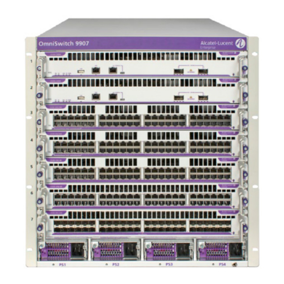
OmniSwitch 9900 Series The Alcatel-Lucent Enterprise OmniSwitch 9907 11 RU modular LAN chassis. OS9907 Chassis Specifications Slots Chassis Management Module (CMM) Slots Chassis Fabric Module (CFM) Slots 4 (Slots CFM 3 and CFM 4 are currently inactive and are reserved for future use.) - Page 8 OS9907 Chassis Specifications Operating Temperature 0°C to 45°C (32°F to 113°F) Storage Temperature 10°C to 70°C (14°F to 158°F) Operating and Storage Humidity 10% to 90% (non-condensing) Altitude 4000m/13,000 feet...
-
Page 9: Chassis Front Panel
Chassis Front Panel OS9907 Front Panel Components Slot 1 Supports Chassis Management Module (CMM) only Slot 2 Supports a CMM (for 1+1 CMM redundancy) or NI module (to maximize port count) Slots 3 through 7 Support NI modules only Slots PS1 through PS4 Support up to four load-sharing chassis power supplies, offering N+1 redundancy Wrist Strap Grounding Connector... -
Page 10: Chassis Rear Panel
Chassis Rear Panel Fan tray slot numbers are printed along the top-rear of the chassis. OS9907 Rear Panel Components Fan Tray Slots 1 through 3 Support three fan trays, with three fans per tray for N+1 fan redundancy Grounding Block Location shown in diagram above Wrist Strap Grounding Connector Location shown in diagram above... -
Page 11: Chassis Rear Panel (Fan Trays Removed)
Chassis Rear Panel (Fan Trays Removed) CFMs are located behind the chassis fan trays. To access a CFM, remove the fan tray in front of the module. See “Removing Fan Trays” on page 50 for more information. CFM slot numbers are printed along the top-rear of the chassis. OS9907 CFM Location Slots CFM1 through CFM4 For CFM module use only. -
Page 12: Chassis Management
Chassis Management OS99-CMM The CMM manages system functions in the chassis. This includes controlling and monitoring NIs, fabric modules (CFMs) and power distribution. The CMM also provides two (2) 40G QSFP+ uplink ports. OS99-CMM CONSOLE VFL / UPLINK CLASS 1 LASER PRODUCT FAB PS TEMP 090992-10 C 0909... - Page 13 LEDs Backlit Status LED Located at the module product name at the upper-left corner of the front panel • Solid Blue: HW OK • Blinking Blue HW Bootup or HW Failure Speed LED (40G) • Solid Green: HW OK • Solid Red: HW Failure •...
- Page 14 QSFP+ Admin Link Status Transceiver Traffic Port Speed LED Display Status 1G/10G (SFP+) 40G/4X10G (QSFP+) Solid Yellow 1G (SFP+) 4X10G (QSFP+) Solid Blue Blinking 10G (SFP+) Green 40G (QSFP+) Blinking 1G (SFP+) Yellow 4X10G (QSFP+) Blinking Blue White 4X10G Note. Because OS99-CMMs provide splitter cable support on QSFP+ ports, port LED behavior for these switches differs from other OS9900 modules.
-
Page 15: Switch Fabric
Switch Fabric OS9907-CFM Each OS9907-CFM installed provides 1280Gbps of switch fabric bandwidth to chassis management and the Network Interface (NI) modules. The chassis provides four (4) OS9907-CFM slots. The modules connect to the chassis mid-plane and are located just behind the system fan trays. CFM Specifications Switch Fabric Bandwidth 1280Gbps... -
Page 16: Ni Modules
NI Modules OS99-XNI-48 OS99-XNI-48 090990-10 C 0 909 0909 0909 0909 0909 0909 0909 0909 90 1 90 1 90 1 90 1 90-1 90-1 90 1 90 1 Port Type Number of Ports Power Consumption 1/10 GigE Base-T 402W OS99-XNI-U48 OS99-XNI-U48 090989-10 C... -
Page 17: Os99-Gni-P48
OS99-GNI-P48 OS99-GNI-P48 090986-10 C 0909 0909 0909 0909 0909 0909 0909 0909 0909 0909 86 1 86 1 86 1 86 1 86 1 86-1 86-1 86-1 86 1 10 C HPoE Port Type Number of Ports Power Consumption 10/100/1000Base-T PoE 54W, excluding any attached Powered Devices (PDs) HPoE Ports... -
Page 18: Ni Module Leds
NI Module LEDs NI Module LEDs Backlight Status LED Located at the module product name at the upper-left corner of the front panel • Solid Blue: HW OK • Blinking Blue HW Bootup or HW Failure Speed LED Located at the left side of the front panel and indicates the maximum port speed for the module (e.g., 10G) •... -
Page 19: Fan Trays
Fan Trays The chassis provides three (3) fan tray slots for chassis air and temperature control. Fan Tray Specifications Number of Fan Tray Slots 3 (with three fans per tray for N+1 fan redundancy) Airflow Direction Front-to-back only Hot Swapping Supported (Three fan trays are required at all times;... -
Page 20: Power Supplies
Power Supplies Note: Mixing of AC and DC power supplies is not supported. Mixing of Hi (240VAC) and Low (110VAC) input is not supported. OS99-PS-A (AC Power Supply) OS99-PS-A Specifications Input Voltage/Current 100 VAC (13.8A) to 240V AC (16.5 A) Max Output Power/Current 1200 W/21.4 A 3000 W/53.5 A... - Page 21 OS99-PS-D Specifications Weight 4.6 lb (2.1 kg) Hot Swapping Supported Provides Power for System and PoE...
-
Page 22: Dc Power Supply Connection
DC Power Supply Connection Connecting a DC Cable Harness to the Chassis Power Supply When plugging in the cable, insert the connector end of the cable harness into the power supply connector until it clicks firmly into place. This is an indication that the connector is secure and properly seated. -
Page 23: Getting Started And Installation
2 Getting Started and Installation... -
Page 24: Getting Started
Getting Started Preparing for the Installation • Alcatel-Lucent Enterprise products must be installed by a professional installer. It is the responsibility of the installer to comply with product specifications and all applicable local and national codes. • When preparing for installation, unpack the product as close as possible to the location where it will be installed. -
Page 25: Items Included
Electrical Surge Warning In order to help protect equipment against electrical surges please take note of the following recommendations and guidelines: 1. Earth grounding of all devices is fundamental to ensure long term reliability. • All electrical equipment must be installed by a qualified, licensed electrician. •... -
Page 26: Airflow Considerations
Airflow Considerations To ensure proper airflow, be sure that the switch is placed in a well-ventilated area and provide minimum recommended clearance at the front, back and sides of the switch. Never obstruct chassis or component air vents. Restricted airflow can cause the switch to overheat, which can lead to system failure and damage to the product. -
Page 27: Mounting The Chassis
To keep the rack from becoming top heavy, install switches toward the bottom of the rack first. Non-Standard Rack-Mounting Hardware All OmniSwitch 10K switches are shipped with integral front rack mount flanges. These flanges support standard 19” rack mount installations. For non-standard rack mount requirements, contact Alcatel-Lucent Enterprise for information on optional hardware availability. -
Page 28: Installing Chassis Components
Installing Chassis Components Installing Fabric Modules To access OS9907-CFM slots, be sure the fan trays covering the slots have been removed. (For information on removing fan trays, refer to “Removing Fan Trays” on page 50.) 1. To install a OS9907-CFM, orient the module so the top (component side) of the circuit board faces left. - Page 29 3. Simultaneously press the top and bottom lock levers until the levers are in the vertical (locked) position and the module is firmly seated in the chassis mid-plane. 4. Hand-tighten the captive screws at the top and bottom of the module. 5.
-
Page 30: Installing Fan Trays
Installing Fan Trays 1. Fan trays are secured by two tabs at the top of the unit and a captive thumb screw at the bottom of the unit. Hold the fan tray by the top and bottom handles. Angle the tray away from the chassis at the bottom, as shown, and insert the tabs at the top of the fan tray slot. - Page 31 2. With the top tabs inserted, push the bottom of the tray into the slot until it is firmly seated.
- Page 32 3. Hand-tighten the thumb screw.
-
Page 33: Installing Modules
Installing Modules 1. To install a module, insert the edges of the circuit board into the grooves at the left and right sides of the chassis. 2. Be sure the lock levers are in the open position and slide the module back until it meets the backplane connectors. -
Page 34: Installing A Power Supply
Installing a Power Supply Once the chassis components have been installed, install the power supplies. Note. When connecting or disconnecting a power supply to/from a chassis, the power supply must first be disconnected from the power source. 1. Remove blank cover panel from the power supply slot (if applicable) and store the cover panel for future use. - Page 35 3. Press the handle up into the vertical (locked) position. The power supply should be fully seated in the chassis backplane. Tighten the thumb screw to secure the power supply. 4. Plug in the power cord and then plug the power cord into an easily-accessible, properly grounded outlet.
-
Page 36: Connections And Cabling
Connections and Cabling Once the switch is properly installed, connect all network and management cables required network applications. Network Cable Installation Warning Never install exposed network cables outdoors. Install network cables per manufacturer requirements. For additional information on cabling for console, EMP, USB, Bluetooth and other connections, refer to the OmniSwitch AOS Switch Management Guide. -
Page 37: Booting The Switch
Booting the Switch To boot the switch, plug all power supply cords into easily-accessible, properly grounded power outlets. (Do not use extension cords.) The switch will power on and boot automatically. Note. If more than one power supply is installed, be sure to plug in each power supply in rapid succession, (i.e., within a few seconds of each other). -
Page 38: The First Login Session
The default welcome banner, which includes information such as the current software version and system date, is displayed followed by the CLI command prompt: Welcome to the Alcatel-Lucent Enterprise OS9900 8.3.1, June 03, 2016. Copyright (c) 1994-2014 Alcatel-Lucent. All Rights Reserved. -
Page 39: Unlocking Session Types
To change the default IP and mask, use the ip interface command. For example: -> ip interface emp address 168.22.2.120 mask 255.255.255.0 Verify the settings using the show ip interface command. See the OmniSwitch AOS Switch Management Guide for additional information regarding EMP port addressing. Note. -
Page 40: Changing The Login Password
Changing the Login Password Change the login password for admin user sessions by following the steps below: 1. Be sure that you have logged into the switch as user type admin (see “Logging In to the Switch” on page 34). 2. -
Page 41: Setting Optional Parameters
Setting Optional Parameters Specifying an Administrative Contact An administrative contact is the person or department in charge of the switch. If a contact is specified, users can easily find the appropriate network administrator if they have questions or comments about the switch. -
Page 42: Working With Chassis Power Budget
Working with Chassis Power Budget The power available to the chassis modules (CMM, CFM, and NI) is based on the user configuration and system environment. Adding additional components (e.g., NI modules, a redundant CMM, or powered POE devices)—as well as removing power supplies—affects the overall power budget for the switch. -
Page 43: Power Over Ethernet (Poe)
3 Power Over Ethernet (PoE) -
Page 44: Managing Power Over Ethernet (Poe)
Managing Power over Ethernet (PoE) Important: Alcatel-Lucent Enterprise recommends that PoE-enabled switches with attached IP telephones have operational power supply redundancy at all times for 911 emergency requirements. In addition, both the switch and the power supply should be plugged into an Uninterruptible Power Source (UPS). -
Page 45: Viewing Power Supply Status
Viewing Power Supply Status To view the type and status for installed power supplies, use the show powersupply command: -> show powersupply Total Power Input Slot Power Used Voltage Type Status Location ---------+---------+--------+---------+--------+--------+----------- 1200 Internal UNPLUG Internal UNPLUG Internal Total 1200 Viewing PoE Status To view current PoE status and settings, including the amount of PoE power available for incoming... -
Page 46: Poe Class Detection
PoE Class Detection Powered devices can be classified into different classes as shown in the table below. Class detection allows for automatic maximum power adjustment based on the power class detected. This will prevent the switch from delivering more than the maximum power allowed based on a device’s class. During class detection, the switch will allocate the maximum amount of power allowed based on the class detected. -
Page 47: Poe Operational Status
PoE Operational Status Enabling PoE By default, PoE is administratively enabled in the switch’s system software. However, in order to physically activate PoE, you must issue the lanpower slot service command on a slot-by-slot basis before any connected devices will receive inline power. To activate power to PoE-capable in a switch, enter the corresponding slot number only. - Page 48 Configuring the Total Power Available to a Slot Like the maximum port power allowance, the system software also provides a maximum slot-wide power allowance. By default, each slot is authorized by the system software to use a number of watts to power all devices connected to its ports depending on which power supply is used.
-
Page 49: Setting Port Priority Levels
Setting Port Priority Levels As not all Powered Devices (PDs) connected to the switch have the same priority within a network setting, the OmniSwitch allows the administrator to specify priority levels on a port-by-port basis. Priority levels include low, high, and critical. The default priority level for a port is low. -
Page 50: Understanding Priority Disconnect
Understanding Priority Disconnect Priority disconnect is used by the system software in determining whether an incoming PD will be granted or denied power when there are too few watts remaining in the PoE power budget for an additional device. For example, if there are only 2 watts available in the current PoE power budget and a user plugs a 3.5W powered device into a PoE port, the system software must determine whether the device will be powered on. - Page 51 Priority Disconnect is Enabled; Same Priority Level on All Devices Reminder. Priority disconnect examples are applicable only when there is inadequate power remaining to power an incoming device. When a PD is being connected to a port with the same priority level as all other in the slot, the physical port number is used to determine whether the incoming PD will be granted or denied power.
-
Page 52: Removing Chassis Components
4 Removing Chassis Components Removing Chassis Components Removing a Power Supply 1. Unplug the power cord from the power source, as well as from the socket on the power supply’s front panel, then loosen the thumb screw at the front of the power supply. Note. - Page 53 Note. Failure to support the chassis as it is being removed may cause the rear of the power supply casing to fall from the slot, resulting in damage to the equipment. 4. If the slot is to remain unused, install a blank cover panel over the space.
-
Page 54: Removing Fan Trays
Removing Fan Trays 1. Loosen the thumb screw. 2. While holding the handles at the top and bottom of the fan tray, pull the bottom handle out until the bottom of the unit disengages from the chassis. Pull the unit out and down until the fan tray is clear of the tabs at the top of the fan tray slot. -
Page 55: Removing Fabric Modules
Removing Fabric Modules To access OS9907-CFM slots, be sure the fan trays covering the slots have been removed. (For information on removing fan trays, refer to “Removing Fan Trays” on page 50.) 1. Loosen the thumb screws at the top and bottom of the module, then pull the lock levers outward to release the CFM from the chassis. - Page 56 1. Grasp the CFM by the front panel and/or lock levers and slide the module out of the slot. Be sure to support the weight of the CFM as it is being removed to prevent the module from falling out of the chassis slot, which can result in damage to the equipment...
-
Page 57: Removing Modules
Removing Modules 1. Loosen the thumb screws at the left and right sides of the module, then press the lock levers outward to release the module from the chassis. 2. Grasp the module by the front panel and/or lock levers and slide the module out of the slot. Be sure to support the weight of the module as it is being removed to prevent the module from falling out of the chassis slot, which can result in damage to the equipment. -
Page 58: Hot Swapping
Hot Swapping General Guidelines • All component removals must have a 30 second interval before initiating another hot swap activity. • All component insertions must have a five minute interval AND an LED state indicating that no errors have occurred before initiating another hot swap activity. •... - Page 59 Existing Slot Hot-Swap/Hot-Insert Compatibility OS99-XNI-U48 OS99-XNI-U48...
-
Page 60: Regulatory Compliance And Safety Information
A Regulatory Compliance and Safety Information... -
Page 61: Compliance And Certifications
• AS/NZ TS-001 and 60950:2000, Australia • UL-AR, Argentina • UL-GS Mark, Germany • GOST, Russian Federation • EN 60825-1 Laser • EN 60825-2 Laser • CDRH Laser Note. For questions regarding these or other certifications, please contact Alcatel-Lucent Enterprise. - Page 62 China RoHS: Hazardous Substance Table...
- Page 63 Taiwan RoHS: Hazardous Substance Table California Proposition 65 Warning WARNING: This product contains chemicals known to the State of California to cause cancer and birth defects or other reproductive harm. Products are packaged using one or more of the following packaging materials: Corrugated Cardboard Corrugated Fiberboard Low-Density Polyethylene...
- Page 64 Waste Electrical and Electronic Equipment (WEEE) Statement The product at end of life is subject to separate collection and treatment in the EU Member States, Norway and Switzerland, and is therefore marked with the symbol: Treatment applied at end of life of the product in these countries shall comply with the applicable national laws implementing directive 2002/96EC on Waste Electrical and Electronic Equipment (WEEE).
- Page 65 Avis de conformitè aux normes du ministère des Communications du Canada Cet èquipement ne dèpasse pas les limites de Classe A d íèmission de bruits radioèlectriques pour les appareils numèriques,telles que prescrites par le RÈglement sur le brouillage radioèlectrique ètabli par le ministère des Communications du Canada.
-
Page 66: Translated Safety Warnings
Translated Safety Warnings Chassis Lifting Warning Two people are required when lifting the chassis. Due to its weight, lifting the chassis unassisted can cause personal injury. Also be sure to bend your knees and keep your back straight when assisting with the lifting of the chassis. - Page 67 Invisible Laser Radiation Warning Lasers emit invisible radiation from the aperture opening when no fiber-optic cable is connected. When removing cables do not stare into the open apertures. In addition, install protective aperture covers to fiber with no cable connected. Français: Des radiations invisibles à...
- Page 68 Proper Earthing Requirement Warning To avoid shock hazard: • The power cord must be connected to a properly wired and earth receptacle. • Any equipment to which this product will attached must also be connected to properly wired receptacles. • Use 22AWG solid copper conductor for ground leads connecting the frame to ground and DC return.
- Page 69 Français: L'électricité statique (ESD) peut endommager les composants du commutateur. Pour cette raison Alcatel-Lucent Enterprise joint à l'envoi du châssis un bracelet antistatique à brancher sur la prise mise à la terre située en bas à droite du commutateur. Vous devrez mettre ce bracelet avant toute intervention hardware.
-
Page 70: Instrucciones De Seguridad En Español
Instrucciones de seguridad en español Advertencia sobre el levantamiento del chasis Se requieren dos personas para levantar el chasis. Debido a su peso, la elevación del chasis sin ayuda puede causar daños corporales. También es seguro doblar sus rodillas y guardar su espalda derecho al ayudar a levantar el chasis. - Page 71 Advertencia sobre una apropiada conexión a tierra Para evitar peligro de descargas: El cable de alimentación debe estar conectado a una toma de alimentación adecuadamente cableada y con toma de tierra. Cualquier equipo al cual se conecte este producto debe estar también conectado a tomas de alimentación adecuadamente cableadas.
Need help?
Do you have a question about the OmniSwitch 9900 Series and is the answer not in the manual?
Questions and answers