Sime MINI 12 BF ErP User Manual
Domestic instantaneous gas water heater
Hide thumbs
Also See for MINI 12 BF ErP:
- User manual (36 pages) ,
- Instructions for use manual (36 pages)

Related Manuals for Sime MINI 12 BF ErP


Summary of Contents for Sime MINI 12 BF ErP
- Page 1 DOMESTIC INSTANTANEOUS GAS WATER HEATER USER’S MANUAL MINI 12 BF ErP Read the technical instruction before installing the appliance Read the user’s instruction before lighting the appliance Cod. 6328403 – 09/2017...
-
Page 2: Table Of Contents
ISO9001 Certified Thank you for purchasing our gas water heater. Read this Manual before installing and operating and keep for future reference. Contents • Special Advice…………………………………………………………………………………………………………..2 • Features &Benefits……………………………………………………………………………………………………2 • Specifications…………………………………………………………………………………………………………….4 • Parts Name ……………………………………………………………………………………………………………….7 • Installation…………………………………………………………………………………………………………………9 • Using Methods………………………………………………………………………………………………………….14 • Safety Cautions…………………………………………………………………………………………………………18 • Maintenance………………………………………………………… …………………………………………………21 • Trouble‐Shooting Guidance ………………………………………………………………………………………22 • Enclose……………………………………………………………………………………………………………………..23 • Packaging and Accessories…………………………………………………………………………………………23 • Electrical diagram…………………………………………………………………………………………… ……..…24 • Conversion instructions…………………………………………………………………………………… ……..…25 ... -
Page 3: Special Advice
Special Advice Read the technical instructions before installing the appliance. Read the user’s instructions before lighting the appliance. The manufacturer or any danger resulted from installation and operations not bear responsibility for any danger resulted from installation and operations not in accordance to this manual. When the outdoors temperature is less than 0℃, the residual water inside the heater must be drained after use. Features & Benefits Micro‐Computer Intelligent Control System The core component of the gas water heater is micro‐computer intelligent control system, which is one of today’s most advanced mechatronic technology. The CPU chipset can analyze automatically and set the optimal working parameter rapidly according to different data such as the flowing water quantity, the pressure situation and the actual inlet water temperature. Digital Control for Automatic Constant Temperature of Outlet Water This function is to monitor the outlet water temperature by a temperature sensor and to transfer the information to the micro‐computer, so that the micro‐computer could adjust the gas and air supply quantity to guarantee the constant outlet water temperature according to the temperature set by the user and the actual inlet water temperature automatically. ... - Page 4 Set Temperature by Touch You could set the required temperature easily by touching the digital display. The setting temperature is from 35℃ to 65℃, which can meet different water temperature requirements with easy operation. Multiple Safety Protection This product has safety protections includes self‐check protection, flame‐out protection, over‐heat protection, accidental power‐cut protection, fan breakdown protection, over electric load ...
-
Page 5: Specifications
Specifications Name Domestic Gas Instantaneous Water Heater Model MINI 12 BF ErP Nominal Heat Input(Hi) 24kW Max Flow Rate(rise 25℃) 12kg/min Appliance Type Gas Type 2H‐G20‐20mbar/3B‐G30‐30mbar/3P‐G31‐37mbar / II2H3P II2H3B/P Gas category Max water pressure Pw=10bar Min water pressure Pw=0.2bar 220VAC,50Hz Electrical power supply Electric power 33W Degree of electrical protection IPX4 Ignition method Water Control Automatic Pules Ignition Destination country GB‐IE‐DK‐FI Gas Inlet G 1 / 2 Cold Water Pipe G 1 / 2 ... -
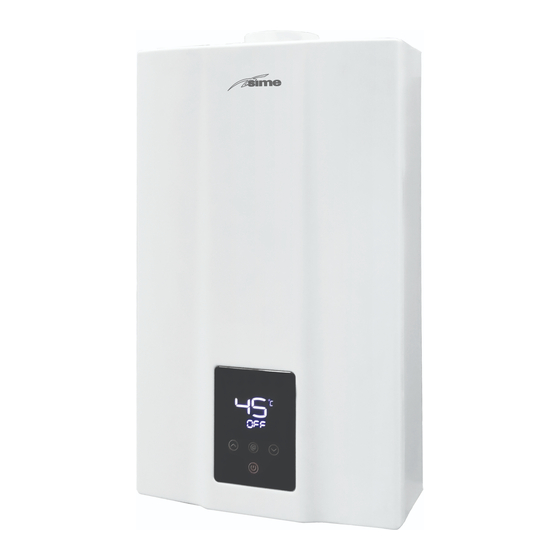
Page 6: Parts Name
Parts Name Fig. 1 (The dimension information is for reference only. Please refer to the actual product.) ... - Page 7 Fig. 2 (Unit: mm) (The dimension information is for reference only. Please refer to the actual product.) ...
-
Page 8: Installation
Installation Contact your local gas dealers or gas management department for a qualified engineer to install the gas water heater (users are recommended not to install by themselves). The installer should be called on to install and adjust the appliance, where appropriate. This product is prohibited to use this gas water heater when flue pipe has not been installed correctly according to instructions. ■ Installation Requirements • The flue of the gas water heater should be installed through an external wall, the heater cannot be installed in outdoors. (Fig.3) Fig. 3 ... - Page 9 • The gas water heater installed in a suitably ventiled room , in accordance with the regulations in force.. It is not allowed to install in the bedroom, underground, bathroom or any other places with poor ventilation. (For B type) • The flue of the heater cannot be connected to a common flue (Fig. 4). • Please don’t install the heater in places where special chemicals are used, such as the laundries or factories etc., otherwise it may cause rusting, shorten the lifetime of the heater, or prevent normal working. (Fig. 5) • Don’t install the heater above the gas stoves or other heat sources. (Fig. 6) • The gas water heater should be kept away from the combustible materials with the distance shown in Fig. 7 at least. • When the installation parts' materials are combustible or flammable should be used frame‐proof board to isolate, heat‐resistant plate and wall gap should be greater than 10mm,and the size of heat plate should be larger than water heater shell for 10mm. (Fig. 8) Fig. 7 Fig. 8 ...
- Page 10 spraying the socket during shower. ■ Installation Method 1. Installation of Gas Water Heater Drill holes in the wall according to Fig. 9, put an expansion bolt into the upper hole and plastic gasket into the lower hole, mount the water heater vertically on the upper bolt without inclination and tighten the lower holes with expansion bolts. ...
- Page 11 • Gas inlet (1) Before connecting the gas supply, check the rating plate on the left side of the right front cover to be sure that the heater is rated for the same gas to which it will be connected. (2) All such pipe shall be either new or previously used for no other purpose than conveying gas; and must be in good condition and free from internal obstructions. Burred ends shall be reamed to the full bore of the pipe. All fittings used shall be of malleable iron, yellow brass, or approved plastic fittings. (3) When your connections are made, check for gas leaks at all joints (this includes all existing piping). Apply soapy water to all gas fittings and gas valve. Soap bubbles are a sign of a leak. ...
- Page 12 3. Installation of the flue: • Flue Duct Installation of Forced‐Exhausted Gas Water Heater (B type) This product is forced exhaust type gas water heater; it can be used only after the flue duct is installed according to the requirements strictly and can exhaust the waste gas to the outdoor area. It’s not allowed to use the gas water heater without installing the flue duct correctly. Please follow the below requirements during the installation of flue duct: (1) Please use the flue supplied by our company, referring to Fig. 11 about the installation method. If the flue duct is too short, you can extend it aptly. Check the flue duct and see if there ...
- Page 13 (1) Please use the flue supplied by our company, referring to Fig. 11 about the installation method. If the flue duct is too short, you can extend it aptly. Check the flue duct and see if there is any damage or leakage every half a year. Install the flue after the heater body is fixed. First, put the fixed flue through the hole in the wall, then insert the elbow into the exhaust outlet of the heater smoothly, the flue end should have a 2°downward inclination (Fig. 11), otherwise the rain may flow into the heater and damage it. (2) The length of the flue duct should be less than 3m, and the number of elbows should not be more than 3 ( one elbow equivalent 1m straight pipe). (3) The distance between the flue duct and the combustible materials should be more than 150mm. If the flue duct needs to get through the combustible materials or wall, it should use the ...
-
Page 14: Using Methods
Using Methods Display Function instruction • Display content instruction • Touch button instructions ... - Page 15 Preparation before ignition • Make sure that the gas used is in accordance with the gas stipulated in the label. • Insert the plug, and then switch on the power.(The buzzer sounds “bi”) • Turn on the gas valve. 3. Temperature Setting • Press the “ “ (on/off) key on the control panel, the screen display and the designed hot water temperature.Press Up “ " or Down ” “ to set the hot water temperature as desired. The lowest hot water temperature of this product is 35°C, highest is 65°C. 35 ~ 48 °C each time you press the button to change 1 °C, 48~65°C each time you press the button to change 5 °C ( that is 48°C、50°C、55°C、60°C、65°C), Each time you press the buzzer ...
- Page 16 5. Use function mode In standby mode (ie, no water status), press the function (@) key, you can select "Auto", "Eco", "normal" three modes in turns, they can cycle, the system default normal mode. Three types of function mode instruction • Normal mode (default): According to the user to set automatic temperature thermostat, then "Auto", "Eco" display lights are not bright. • Auto mode: ("Auto" display lights is bright.) According to the inlet water temperature, the system automatically adjusts the setting temperature (as shown in Table 1), allowing users to get the most comfortable hot water supply in anytime. Table 1 Temperature mapping table No. Local Water Temperature Corresponding Temperature 1 ≤ 15 C C 2 C‐21 C C 3 C‐27 C C ...
-
Page 17: Safety Cautions
6. Inquiry the cumulative amount of gas and water In working statement, @ buttons can inquire about the cumulative water consumption and gas consumption. Click the @ key to query cumulative amount of using water information, press @ key again can be inquired accumulated gas consumption information. Press the third time for the @ button or no operation for 20s, can exit the inquiry function. Note: • Real‐time gas consumption show the basic unit of m³/h • Real‐time hot water production show the basic unit of L/min • Cumulative amount of using water and gas consumption show the basic unit of m³, When the display numbers reach 999m³,water record is automatically cleared. For example, when the query information display "Water production 180m³", represents a total cumulative amount of water heater 180m³. When real‐time gas consumption information shows "volume 8.3m³", it indicates the water heater cumulative total gas consumption 8.3m³. ... - Page 18 • Close down the cold water valve sans 3, if a valve is installed on the hot water circuit, open it. • If there is a control valve 4 at the hot water outlet, please open it. • Turn the drain valve 5 and take off, replace it after the residual water is completely discharged. Fig.14 ...
- Page 19 ■ Gas accident prevention • Check if the flame of burner is out after use and do not forget to turn off the gas valve (Fig. 15) and power. • Always check the gas connectors for gas leakage with soapsuds. If any gas leakage is detected, open the room windows and doors. At that moment, do not ignite or operate the switch of electric appliances or plugs because the flame or electric spark can result in explosive accidents. (Fig. 16) • Heaters must use the gas type which the heater is designed to use, different type of gas or the same gas in different place must not be used. • Always check the gas pipe and change the pipe every year to avoid gas leakage due to cracking. • If the flame goes unsteadily, stop using the water heater and contact the qualified service facility for repair or adjustment. ...
- Page 20 ■ Carbon Monoxide toxicosis prevention • This product must exhaust the waste gas to the outdoor area during working, so the flue duct must be connected to the joint on the top of the water heater to exhaust the waste gas out to the outdoor area, keep the air fresh indoor and avoid incomplete combustion. Otherwise, it will cause danger or even death. • Too low or too high gas pressure leads to abnormal combustion. At that moment, stop using the water heater and get in contact with a service engineer. • Dust and accelerated carbon would block the heat exchanger due to long time use, and affect the combustion performance, causing the Carbon monoxide to increase. Therfore, contact a qualified person to clean and clear the dust and accelerated carbon every half year to ensure the combustion product discharges smoothly. • The heater must be installed vertically, if inclined it will make the flame touch the heat exchanger and cause the monoxide to increase. ...
-
Page 21: Maintenance
Maintenance ▲ The appliances should be checked and maintained periodically by a competent person ▲Check the gas tube/pipe regularly for any defect. Contact service center for any doubt. Always check the gas pipe for cracks. ▲ Always check for leaking water. ▲ Ask qualified technicians to examine the burner, flue and fan once a year. ▲ Always check the flame inside the water heater for any abnormal conditions. ▲ Keep the cover of the water heater clean. ▲ This product uses water pressure to open the channels. When the water pressure is lower than 0.2bar, the heater cannot be ignited. ▲ The drain valve is dripping. When the water pressure is too high, the drain valve will release the water so as to reduce the pressure to protect the heater. ▲ When the heater is supplying hot water to several points at the same time, the hot water flow would be reduced, or no hot water will issue at all. ▲ When the temperature outside is too low and the exhausted gas meets the cold air, it will be condense as white fog. This is normal. ▲ When the water temperature is too high, set to a lower temperature and reduce the water tap. If the water temperature outlet is too high, please open the tap to reduce the temperature. ▲ When the water temperature is too low, and the hot water volume is so high so that it exceeds the heater’s heating power, the outlet water will be not hot enough, please reduce the water volume. ▲ In order to ignite immediately, the fan in the appliance will delay running for a long time and then stop automatically. This is normal. ... -
Page 22: Trouble-Shooting Guidance
Trouble‐Shooting Guidance Errors Solutions Causes Turn on the main gas valve Main gas valve off • widely or change new gas. Main gas valve half Turn on the main gas valve ... -
Page 23: Enclose
Enclose: Explanation of the Error Codes In the process of using, the display of the fire, wind and other patterns disappeared, because the security device has been caused by action. Display flashing fault code shows that the failure of its occurrence, the reason for the exception. Fault code has been flashing when failure. On such occasions, please turn off the hot water value and then open, or close / open the monitor, and then operate 1‐2 times. If the display still show the fault code, please be sure to close the water valve and valve, unplug the power plug, and contact the after‐sales service. Error Code Explanation 01 Inlet water temperature sensor breaks down 10 Detect a flame signal through pre‐check 11 Ignition fails 12 Normal combustion flames out accidentally 13 Thermostat fault protection 32 Fan blocking protection 40 Fan or its drive circuit breaks down Over high temperature protection 50 (outlet > 80°C) Over high temperature protection(inlet > 65°C) 51 ... -
Page 24: Electrical Diagram
Electrical diagram • If change, No special advice! ... -
Page 25: Conversion Instructions
Conversion instructions ... - Page 26 Technical instruction Step 1 1.Screw off the front panel and disconnect the display and control unit terminal. Open front cover Step 2 1.Screw off the gas tube assembly① and take it out②. Replace gas 2.Change to the matched gas ejector tube assembly. tube assembly Note: It's necessary to examine the air tightness after change, to check the seal (pic 1) ring on the gas control system installed well to prevent gas leakage. Step 3 1.Connect display and control unit Setting the gas type, 2.Volume selection: Within 10s, after the system is powered on but switched volume, and model ...
- Page 27 secondary pressure of different gas type and volume. Step 4 1. Check the airproof of finished product ensure no gas leakage. Assemble front cover 2. Assemble front cover, tighten screws of front cover. Note 1. When replace with new gas tube assembly, notice whether the seal ring on gas control system assembly is fixed well. 2. Check the airproof of finished product ensure no gas leakage. 3. After finish replacing the conversion kits, replace the corresponding labels on the appliance, for example, data plate. 4. This instruction is for reference only,take the material object as the standard. ▲Attention: Conversion to other gases shall be carried out by a qualified installer, asdescribed in installation instructions...
- Page 28 Fonderie Sime S.p.A Via Garbo, 27 ‐ 37045 Legnago (VR) Telefono +39 0442 631111 ‐ Fax +39 0442 631292 www.sime.it ...
Need help?
Do you have a question about the MINI 12 BF ErP and is the answer not in the manual?
Questions and answers