Table of Contents
Advertisement
Quick Links
1M23N25803
S-FHSS Air System
TM-FH RF Module
and
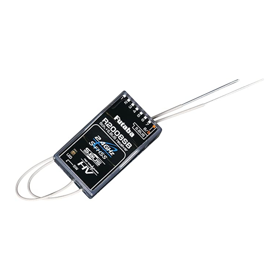
R2006GS Receiver
Instruction Manual
Applicable systems:
T9C, T9Zwc2, T10C
Contents and Technical Specifications
Your 2.4GHz system includes the following components:
R2006GS Receiver
Easy Link Swich
Mini screwdriver
Range Check Swich
TM-FH RF Module
Special Markings;
Pay special attention to the safety at
the parts of this manual that are
indicated by the following marks.
[Symbol]
; Prohibited
; Mandatory
Important: The 2.4GHz band offers different characteristics than
that of the conventional 50MHz and 72MHz. As such, we strongly
encourage you to read this manual carefully prior to utilizing the TM-
FH and R2006GS S-FHSS system.
Thank you for purchasing the TM-FH 2.4GHz transmitter module and
R2006GS receiver. This system is designed for use only with the Futaba
transmitters indicated elsewhere in this manual. In order to use the TM-
FH transmitter module, you will need to carefully remove the existing
transmitter module and replace it with the TM-FH transmitter module.
The receiver R2006GS, as the model number indicates, is capable of
controlling models up to six channels. Please note: The installation of
special attention to the information contained within this manual in order
Note:
Futaba S-FHSS system and FASST system are not compatible each other.
Features:
• 2.4GHz Spread Spectrum radio communication system.
• Exclusive ID code to avoid interference from other S-FHSS systems.
• Fail Safe (F/S) function (for throttle channel)-F/S, Battery F/S
• Dual antenna diversity (R2006GS)
Usage Precautions:
1) Prior to utilizing any radio control system, it is strongly recommended
that you read and abide by the Safety Code created by the Academy of
Model Aeronautics as well as any site specific rules and regulations that
might exist. Doing so will greatly increase your enjoyment of the hobby.
2) In order to maintain complete control of your aircraft it is important that
it remains visible at all times. Flying behind large objects such as build-
ings, grain bins, etc. is not suggested. Doing so may result in the reduc-
tion of the quality of the radio frequency link to the model.
3) Please do not grasp the transmitter module's antenna during flight. Do-
ing so may degrade the quality of the radio frequency transmission.
Specifications:
TM-FH RF Module-
• Communication system: one-way communication
• Antenna: 1/2 wavelength di-pole
• Current consumption: 150mA maximum
• Setting switch for Fail Safe (F/S) setting and range check
R2006GS Receiver-
• Dual antenna diversity
• Power requirement: 4.8V or 7.4V battery or regulated out-
(*1)
put from ESC, etc.
• F/S and Battery F/S function for throttle channel (channel
three)
• Size: 1.70 x 0.98 x 0.35 in. (43.1 x 25.0 x 8.8 mm)
• Weight: 0.30 oz. (8.5g)
(*1)
Be sure that when using ESC's regulated output the capacity
of the ESC must meet your usage condition. Never use dry cell
with the receiver's operation.
Mark
Meaning
Procedures which may lead to a dangerous condition and cause
death or serious injury to the user if not carried out properly.
Procedures which may lead to a dangerous condition or cause death
or serious injury to the user if not carried out properly, or procedures
where the probability of superficial injury or physical damage is high.
Procedures where the possibility of serious injury to the user is
small, but there is a danger of injury, or physical damage, if not
carried out properly.
Installing the TM-FH Module and R2006GS Receiver
Attachment of the Module
CAUTION
Be sure to turn off the power of the transmitter before you
install or replace the module.
1
Ensure that the transmitter is set to the PPM (pulse
position modulation) mode. Please consult the
respective owner's manual for your particular transmitter
for information on how to do so.
2
While it is unlikely that the existing transmitter antenna
will interfere with the radio frequency transmission of
the TM-FH, we suggest removing it from the transmitter if
possible as a precaution.
3
Next, with the transmitter's power off, remove the
existing transmitter module and install the TM-
FH module with care so that the connector pins of the
transmitter won't be damaged.
Do not bend the connector pins.
Antenna of TM-FH
1
As with all radio frequency transmissions, the
strongest area of signal transmission is from the sides
of the TM-FH transmitter module's antenna. As such, the
antenna should not be pointed directly at the model. If
your flying style creates this situation, easily move the
antenna to correct this situation.
2
Please do not grasp the transmitter's antenna during
flight. Doing so may degrade the quality of the RF
transmission to the model.
Easy Link
Each TM-FH transmitter module has an individually assigned
unique ID code. In order to start operation, the receiver must
be linked to the respective TM-FH's ID code. Once the linking
is done, the ID code is stored in the receiver and the re-linking
TM-FH module.
Additionally, it is important to note that this TM-FH and
R2006GS receiver set has already been linked by the factory.
Should you wish to re-link them, or if you have purchased
a separate receiver and would like to link it to this TM-FH,
please adhere to the following procedure.
WARNING
After the linking is done, please cycle receiver power and
check if the receiver to be linked is really under the con-
trol by the transmitter to be linked.
Do not perform the linking procedure with motor's main
wire is connected or the engine is operating as it may re-
sult in serious injury.
1
After the TM-FH module has been installed into the
transmitter, using the aforementioned steps, turn
on the transmitter. The RF output confirmation display
of the transmitter is confirmed. If not, power down the
transmitter and turn it on once again.
2
When the transmitter is turned on, the receiver is
turned on.
3
With the receiver on, press and hold the Easy Link
button, located on the receiver, for approximately two
seconds and release it. Then the receiver starts linking
procedure. When the linking process has been completed,
the LED on the receiver will change to a solid green and
the linking is established.
Receiver Installation
You will note that the R2006GS differs in appearance from
the standard Futaba receiver. The R2006GS incorporates two
separate antennas into its design which enables it to receive
the radio frequency transmission at two different locations.
Futaba's dual antenna diversity, or DAD, then seamlessly
selects the best signal reception between these antennas to
ensure that there is no loss of signal.
*Must be kept as straight as possible.
Antenna
Coaxial cable
To obtain the best results from the R2006GS receiver, please
refer to the following instructions and precautions:
1
Install the receiver in the aircraft using the same
methodology as you would handle a standard receiver.
That is, make sure that you wrap the receiver in foam
rubber or other such material to make it less susceptible
to vibration, etc.
2
Ensure that the two receiver antennas are kept as
straight as possible. This will allow you to obtain the
maximum effective range from your model.
3
If possible, please make sure that the two antennas
are placed at 90 degrees to each other. Please note:
This is not a critical figure, however, the most important
thing is to keep the antennas away from each other as
much as possible.
4
If your model includes metal conductive items which
may impact the receiver's ability to clearly receive the
radio frequency signal, we suggest mounting the receiver
Advertisement
Table of Contents

Related Manuals for FUTABA S-FHSS


Summary of Contents for FUTABA S-FHSS
- Page 1 Thank you for purchasing the TM-FH 2.4GHz transmitter module and sult in serious injury. CAUTION R2006GS receiver. This system is designed for use only with the Futaba S-FHSS Air System transmitters indicated elsewhere in this manual. In order to use the TM-...
- Page 2 For further assistance transmitter. you may also refer to your hobby dealer, or contact the Futaba * Note: Do not press and hold the "F/S, Range" switch prior to turning Service Center at the web site, fax or telephone number below: on the transmitter.
Need help?
Do you have a question about the S-FHSS and is the answer not in the manual?
Questions and answers