
Related Manuals for AlazarTech ATS9371


Summary of Contents for AlazarTech ATS9371
- Page 1 ATS9371 User Manual 12 Bit, 2 Channel, 1 GS/s Waveform Digitizer for PCI Express Gen 3 Bus Written for Hardware Version 1.5 September 2018 Edition...
- Page 2 Canada H9R 4S2 Telephone: (514) 426-4899 Fax: (514) 426-2723 E-mail: sales@alazartech.com Web site: www.alazartech.com To comment on the documentation for ATS9371, send e-mail to support@alazartech.com. Information required when contacting AlazarTech for technical support: Owned by: Serial Number: Purchase Date: Purchased From:...
- Page 3 AlazarTech will pay the shipping costs of returning to the owner parts that are covered by warranty. AlazarTech believes that the information in this document is accurate.
- Page 4 Any action against AlazarTech must be brought within one year after the cause of action accrues. AlazarTech shall not be liable for any delay in performance due to causes beyond its reasonable control. The warranty provided herein does not cover damages, defects, malfunctions, or service failures caused by owner’s failure to follow the AlazarTech...
- Page 5 UP OR SHUT DOWN MECHANISMS. BECAUSE EACH END- USER SYSTEM IS CUSTOMIZED AND DIFFERS FROM ALAZARTECH’s TESTING PLATFORMS AND BECAUSE A USER OR APPLICATION DESIGNER MAY USE ALAZARTECH PRODUCTS IN COMBINATION WITH OTHER PRODUCTS IN A MANNER NOT EVALUATED OR CONTEMPLATED BY...
-
Page 6: Compliance
Federal Communications Commission (FCC) and Innovation, Science and Economic Development (ISED) Canada. Changes or modifications not expressly approved by AlazarTech Inc. could void the user’s authority to operate the equipment under the FCC/ISED Rules. - Page 7 Innovation, Science and Economic Development Canada This Class A digital apparatus meets all requirements of the Canadian Interference-Causing Equipment Standard (ICES-003). Cet appareil numérique de la classe A respecte toutes les exigences du Règlement sur le matériel brouilleur du Canada. ATS9371 User Manual...
- Page 8 EU, or where compliance is not required as for electrically benign apparatus or cables. To obtain the DoC for this product, click Declaration of Conformity at www.alazartech.com/support/documents.htm. This web page lists all DoCs by product family. Select the appropriate product to download or read the DoC.
-
Page 9: Table Of Contents
What You Need to Get Started ............ 9 Unpacking .................. 10 Installing the ATS9371 ............... 11 Installing the ATS9371 in a Linux System ........20 Updating ATS9371 Driver ............23 CHAPTER 3 HARDWARE OVERVIEW ........24 Physical Overview ..............26 Status LEDs ................ -
Page 10: Change Log
Change Log This is the first edition of this manual ATS9371 User Manual... -
Page 12: Chapter 1 Introduction
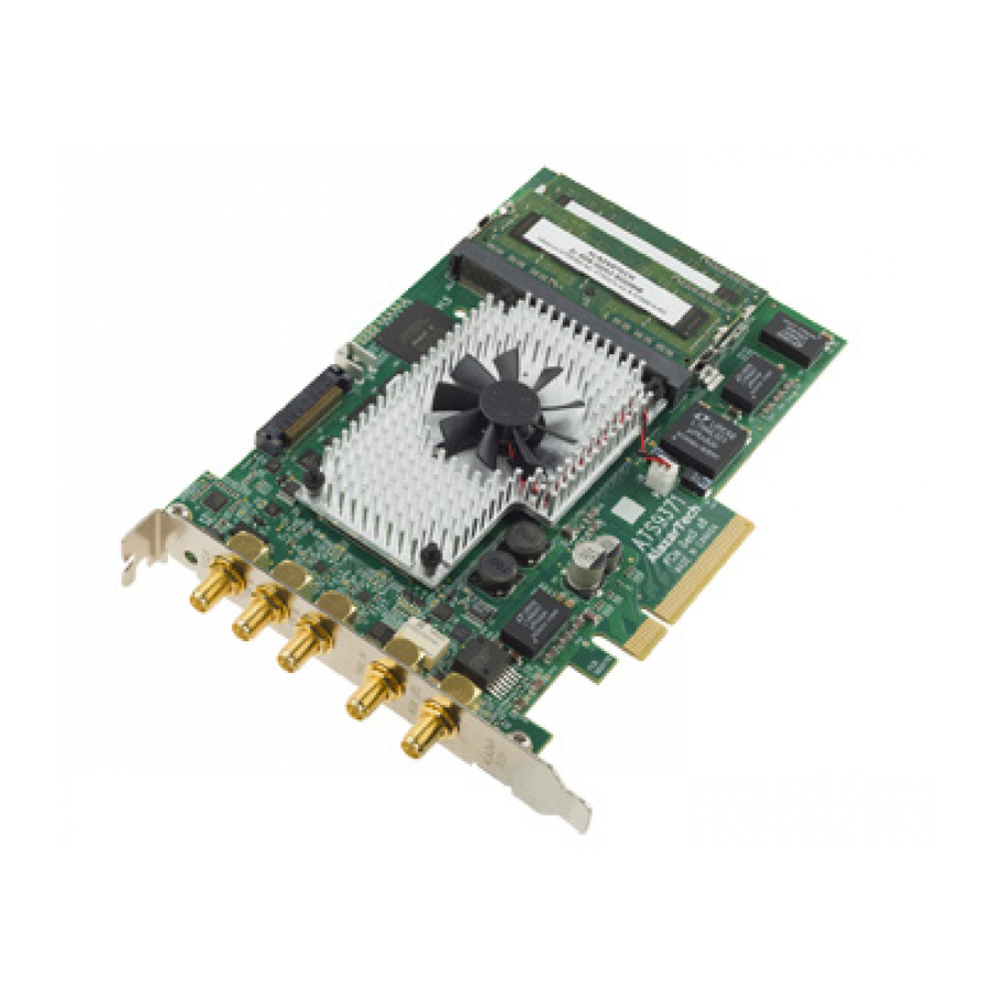
Chapter 1 Introduction This chapter describes the ATS9371 and lists additional equipment. Note: The Board color can be GREEN or BURGUNDY ATS9371 User Manual... -
Page 13: About Your Ats9371
About Your ATS9371 Thank you for your purchase of an ATS9371. This PCI Express (PCIe Gen3 x8) based waveform digitizer has the following features: • Two 12-bit resolution analog input channels • Real-time sampling rate of 1 GS/s to 1 KS/s with internal... -
Page 14: Ats9371 Export Control Classification
Area Control List Sanctions List. Furthermore, if the end-use of ATS9371, in part or in its entirety, is related to the development or deployment of weapons of mass destruction, AlazarTech is obliged to apply for an export permit. ATS9371 User Manual... -
Page 15: Acquiring Data With Your Ats9371
You can acquire data either programmatically by writing an application for your ATS9371 or interactively with the AlazarDSO software. If you want to integrate the ATS9371 in your test and measurement or embedded OEM application, you can program ® ®... - Page 16 Interactively Controlling your ATS9371 The AlazarDSO oscilloscope emulation software for Windows allows you to interactively control your ATS9371 as you would a desktop oscilloscope. Under Linux, an application named Alazar Front Panel is available. Note that Alazar Front Panel has a limited feature set.
- Page 17 AlazarTech PCIe digitizers on a CUDA compatible GPU. Using pinned buffers, ATS-GPU can move data at rates up to 4 GB/s for ATS9371. To help you get started, ATS- GPU-BASE comes with an example of a user application that performs very simple signal processing (data inversion) you can use or modify.
-
Page 18: Optional Upgrades
Optional Upgrades AlazarTech offers the following upgrades and accessories for use with your ATS9371 digitizer: • ATS9371: External Clock Upgrade (300 MHz to 1 GHz) • ATS9371: Screened External Clock Upgrade (100 MHz to 1 GHz) ATS9371 User Manual... -
Page 19: Chapter 2 - Installation And Configuration
Chapter 2 - Installation and Configuration This chapter describes how to unpack, install, and configure your ATS9371. ATS9371 User Manual... -
Page 20: What You Need To Get Started
What You Need to Get Started To set up and use your ATS9371, you will need the following: • One or more ATS9371 digitizers (Note: The Board color can be GREEN or BURGUNDY) • ATS9371 Installation Software on USB Disk (or downloaded software from www.alazartech.com/support/downloads.htm) -
Page 21: Unpacking
• Remove the digitizer from the package and inspect the digitizer for loose components or any other sign of damage. Notify AlazarTech if the digitizer appears damaged in any way. Do not install a damaged digitizer into your computer. •... -
Page 22: Installing The Ats9371
ATS9371 on a CUDA compatible GPU c. The ATS-GMA library, which enables you to DMA data from the ATS9371 on an AMD Radeon Pro GPU card for OpenCL™-based development The following paragraphs will guide you through this process in a step-by-step manner. - Page 23 8-lane or 16-lane connector on the motherboard. Make sure that your computer is powered off before you attempt to insert the ATS9371 digitizer in one of the free PCI Express slots. For best noise performance, leave as much room as possible between your ATS9371 and other hardware.
- Page 24 2. Install ATS9371 software driver Linux users: skip to Installing the ATS9371 in a Linux System The following instructions guide you through the process of installing the ATS9371 in a computer running Windows 10, 8, 7, Windows Server 2013, Windows Server 2010, or Windows Server 2008 R2 operating systems.
- Page 25 If it does not auto-run, manually run the Autorun.exe program on the USB flash drive. The following splash screen will be displayed. Click Install Driver. c) The Select Driver window will appear. Select ATS9371 and click OK. ATS9371 User Manual...
- Page 26 The User Account Control pop-up window will show up asking for installation permissions. Click YES to continue installation. e) Windows will install the ATSApi library. ATS9371 User Manual...
- Page 27 Alazar Technologies Inc.’ Note: If you have Windows 10 v.1607 or later, you cannot install AlazarTech driver versions older than 6.0.0. This is normal behavior. This limitation is due to Microsoft’s driver code signing policy change, which now requires a SHA-2 code signing certificate.
- Page 28 The ATS9371 Device Installer box will display the installation progress of the driver files. Congratulations! The following final screen will confirm that the driver has been successfully installed. ATS9371 User Manual...
- Page 29 3. Install AlazarDSO software that allows you to setup the hardware, acquire signals and view and archive them If you are installing from the USB flash drive shipped with the ATS9371 digitizer, run the Autorun.exe: • Click on Install AlazarDSO •...
- Page 30 ATS-SDK included with your ATS-GMA. Follow the instructions on the screen. Note that you must have already installed the ATS9371 drivers for any of the sample programs included with the ATS-SDK or ATS- GPU or ATS-GMA to work properly.
-
Page 31: Installing The Ats9371 In A Linux System
Installing the ATS9371 in a Linux System To get the latest version of all AlazarTech Linux Packages, please go to: ftp://release@ftp.alazartech.com/Outgoing/Linux The AlazarTech software components used to communicate with digitizer boards and make acquisitions are divided into several packages: • libats: The shared library that allows user programs to communicate with the board drivers. - Page 32 To install an ATS9371 on your Linux system, follow the next steps: 1. Connect one or several ATS9371 in your computer 2. Start your computer, and install all the software packages for your ATS9371.
- Page 33 Installation Troubleshooting If you are experiencing difficulties using AlazarTech digitizers on your Linux system, please ensure that the following packages are all installed: • alazar-front-panel • libats • driver package for your board (with the right kernel version) If these packages are installed, but the AlazarFrontPanel...
-
Page 34: Updating Ats9371 Driver
Take note of your serial number and go to www.alazartech.com/UserHome?tab=2. You must be logged into your My AlazarTech account in order to register a product. If you do not have an account, sign-up for one here: www.alazartech.com/Regstart... -
Page 35: Chapter 3 Hardware Overview
Chapter 3 Hardware Overview This chapter includes an overview of the ATS9371, explains the operation of each functional unit making up your ATS9371, and describes the signal connections. Following is a high-level block diagram of ATS9371. ATS9371 User Manual... - Page 36 ATS9371 User Manual...
-
Page 37: Physical Overview
AUX I/O: An auxiliary input/output connector It also has a bracket LED that can be software controlled, and is used for identification. ATS9371 has two memory SO-DIMM connectors on the back of the PCB. Lastly, ATS9371 has various status LEDs on the edge of the PCB that can be used for debugging. - Page 38 Figure 2 - Mechanical Drawing ATS9371 User Manual...
-
Page 39: Status Leds
Status LEDs ATS9371 has 9 Status LEDs. Descriptions are provided below in the order in which they appear, from left to right: Figure 3 - ATS9371 Status LEDs • PS3: Power Monitor error output from the board. This LED being red indicates that there is an overheating or power supply issue. - Page 40 PS1: Power Monitor error output from the board. This LED being red indicates that there is an overheating or power supply issue. Refer to Figure 4 – Flowchart for Power Monitor Status LEDs for steps to follow if this LED is red. ATS9371 User Manual...
- Page 41 Note: for Power Monitor error outputs, the Status LED remains on even after the issue is resolved. To turn off the Status LED, you must press the “Clear Int.” button in the AlazarDSO Power Monitor plug-in or restart the computer. ATS9371 User Manual...
-
Page 42: Signal Connections
Use the TRIG IN input for an external trigger only; data on the TRIG channel cannot be digitized. If External Clock Upgrade is installed on your ATS9371, use the ECLK input for clocking the ATS9371 in applications that require an external clock. Consult the chapter Optional External Clock details on various types of clocking schemes available. -
Page 43: Analog Input
For accurate measurements, make sure the signal being measured is referenced to the same ground as your ATS9371 by attaching the cable’s ground shield to the signal ground. The External Trigger input (labeled TRIG IN) has a ±2.5 V analog Input range with 50 Ω... -
Page 44: Calibration
2. If not, perform calibration, i.e. make adjustments to the circuit until it is within specifications again 3. If any adjustments have been made, verify if the ATS9371 is within specifications Recalibration must be performed at AlazarTech factory. -
Page 45: Optional External Clock
Optional External Clock ATS9371 PCI Digitizer optionally allows you to supply the ADC clock. This option is extremely important in many RF applications in which phase measurements must be made between the inputs themselves or between the inputs and an external event. - Page 46 10 MHz Clock Reference ATS9371 allows the user to synchronize the sampling clock to an external 10 MHz reference signal. This is useful in many RF applications.
-
Page 47: Oct Ignore Bad Clock
Note: You must have ATS-SDK version 7.1.3 or later as well as ATS9371 Firmware version 26.04 or later, and driver version 6.00.01 or later in order to use OCT Ignore Bad Clock. ATS9371 User Manual... -
Page 48: Chapter 4 Specific Features
Chapter 4 Specific Features This section contains information about features specific to AlazarTech digitizers and ATS9371 in particular. ATS9371 User Manual... -
Page 49: Streaming Data Across The Bus
Streaming Data Across the Bus One of the most unique features of the ATS9371 is its on-board, dual-port acquisition memory that can act as a very deep Data FIFO and the associated Dual-DMA engine. This combined by the advanced, fully asynchronous software driver allows data transfer to host PC memory without any appreciable “in-process”... - Page 50 This requires a software handshake which is heavily dependent on the operating system response time. ATS9371 solves this problem by providing a FIFO and an advanced dual-DMA engine that can stream data to PC host memory at up to 6.8 GB/s (exact rate is motherboard dependent).
- Page 51 ATS9371’s proprietary AutoDMA circuitry allows the acquisition system to be re-armed by a hardware command and data transfer to be initiated by the hardware itself, thus removing virtually all “in- process” software involvement. Figure 5 - AutoDMA acquisition and transfer cycle...
- Page 52 Continuous AutoDMA is also known as the data streaming mode. In this mode, data starts streaming across the PCI bus as soon as the ATS9371 is armed for acquisition. It is important to note that triggering is disabled in this mode.
- Page 53 This is very useful in cases where the acquisition data rate is higher than the disk writing speed, but the total acquisition size is less than the free RAM of the computer. This module is accessed by clicking on Tools >> Stream To Memory… ATS9371 User Manual...
-
Page 54: On-Fpga Fft
It is also possible to DMA both frequency and time domain data. This allows users to verify FPGA-based FFT operation during algorithm development. Figure 6 - On-FPGA FFT Block Diagram ATS9371 can perform 250,000 4096 point FFTs per second. ATS9371 User Manual... -
Page 55: Fpga Customization
FPGA Customization ATS9371’s FPGA is not user-programmable, but AlazarTech provides a service of FPGA customization. For more information, contact the AlazarTech factory. ATS9371 User Manual... -
Page 56: Appendix A - Specifications
Appendix A - Specifications This appendix lists the specifications of the ATS9371. These specifications are typical at 25 °C unless otherwise stated. The operating temperature range is 0 to 55 °C. Minimum Requirements Windows 10, Windows 8.x, Windows 7, Windows Server 2013, Windows Server 2010... - Page 57 Record length must be a minimum of 256 points. There is no upper limit on the maximum record length. Number of Records Software selectable from a minimum of 1 to a maximum of infinite number of records Pre-trigger depth From 0 to 4088 ATS9371 User Manual...
- Page 58 Dynamic Parameters Typical values measured on 400 mV range of CH A of a randomly selected ATS9371. Input signal was provided by an SRS SG384 signal generator, followed by a 9-pole, 100 MHz band-pass filter (TTE Q36T-100M- 10M-50-720BMF). Input frequency was set at 99.9 MHz and output amplitude was approximately 95% of the full scale input.
- Page 59 Trigger level accuracy ±5%, typical, of full-scale input range of the selected trigger source Bandwidth 250 MHz Trigger Delay Software selectable from 0 to 9,999,999 sampling clock cycles. Has to meet alignment requirements (see ATS-SDK Guide for more information) ATS9371 User Manual...
- Page 60 Bandwidth (-3 dB) DC - 250 MHz Input range ±2.5 V or TTL Input, software selectable For TTL, ATS9371 accepts 3.3 V TTL and is 5 V-compliant. Pulse amplitude must be > 2.0 Volts. DC accuracy ±10% of full-scale input Input protection ±8 V (DC + peak AC without external...
- Page 61 One ATS9371 PCI Express Card One ATS9371 Install Disk on USB flash drive Supported Linux Distributions AlazarTech offers ATS9371 binary drivers for most of the popular Linux distributions, such as CentOS, Ubuntu,... Users can download the binary driver for their specific distribution by choosing from the available drivers here: ftp://release@ftp.alazartech.com/outgoing/linux...
-
Page 62: Appendix B - Benchmarks
Given the constantly changing nature of computers, these benchmarks are provided as a reference only and AlazarTech assumes no liability in case the computer you purchase behaves differently than what was observed in AlazarTech’s laboratory. - Page 63 ALAZAR TECHNOLOGIES INC. 6600 Trans-Canada Highway Suite 310 Pointe-Claire, QC CANADA H9R 4S2 Tel: (514) 426-4899 Fax: (514) 426-2723 E-mail: sales@alazartech.com Web: www.alazartech.com...
Need help?
Do you have a question about the ATS9371 and is the answer not in the manual?
Questions and answers