
Related Manuals for AlazarTech ATS9626


Summary of Contents for AlazarTech ATS9626
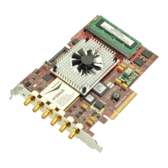
- Page 1 ATS9626 User Manual 16 Bit, 250 MS/s Waveform Digitizer for PCI Express Bus Written for Hardware Version 1.2 June 2013 Edition Part Number: 9360-USR-1...
- Page 3 Canada H9R 4S2 Telephone: (514) 426-4899 Fax: (514) 426-2723 E-mail: info@alazartech.com Web site: www.alazartech.com To comment on the documentation for ATS9626, send e-mail to support@alazartech.com. Information required when contacting AlazarTech for technical support: Owned by: ___________________________ Serial Number: ___________________________ Purchase Date:...
- Page 4 Important Information Warranty The ATS9626 is warranted against defects in materials and workmanship for a period of one year from the date of shipment, as evidenced by receipts or other documentation. AlazarTech, Inc. will, at its option, repair or replace equipment that proves to be defective during the warranty period.
- Page 5 Warning Regarding Use of AlazarTech Products ALAZARTECH, INC. PRODUCTS ARE NOT DESIGNED WITH COMPONENTS AND TESTING FOR A LEVEL OF RELIABILITY SUITABLE FOR USE IN OR IN CONNECTION WITH SURGICAL IMPLANTS OR AS CRITICAL COMPONENTS IN ANY LIFE SUPPORT SYSTEMS WHOSE FAILURE TO PERFORM CAN REASONABLY BE EXPECTED TO CAUSE SIGNIFICANT INJURY TO A HUMAN.
-
Page 6: Compliance
Classification requirements are the same for the Federal Communications Commission (FCC) and the Canadian Department of Communications (DOC). Changes or modifications not expressly approved by AlazarTech Inc. could void the user’s authority to operate the equipment under the FCC Rules. - Page 7 To obtain the DoC for this product, click Declaration of Conformity at http://www.alazartech.com/support/documents.htm. This web page lists all DoCs by product family. Select the appropriate product to download or read the DoC.
-
Page 8: Table Of Contents
What You Need to Get Started ..........10 Unpacking .................. 11 Installing the ATS9626 ............... 12 Installing the ATS9626 in a Linux System ........21 Compiling the ATS9626 Linux Driver ......... 22 Updating ATS9626 Driver ............23 CHAPTER 3 - HARDWARE OVERVIEW ........25 Input Connectors ................ -
Page 9: Chapter 1 - Introduction
Chapter 1 - Introduction This chapter describes the ATS9626 and lists additional equipment. ATS9626 User Manual... -
Page 10: About Your Ats9626
About Your ATS9626 Thank you for your purchase of an ATS9626. This PCI Express (PCIe x8) based waveform digitizer has the following features: Two 16-bit resolution analog input channels Real-time sampling rate of 250 MS/s to 1 KS/s with... - Page 11 If your application requires more than two channels for data acquisition, you can synchronize multiple digitizers on all platforms using a Master/Slave SyncBoard 9626. Detailed specifications of the ATS9626 digitizers are listed in Appendix A, Specifications. ATS9626 User Manual...
-
Page 12: Acquiring Data With Your Ats9626
You can acquire data either programmatically by writing an application for your ATS9626 or interactively with the AlazarDSO software. If you want to integrate the ATS9626 in your test and measurement or embedded OEM application, you can program the digitizer using C/C++, MATLAB or LabVIEW for Windows or C and LabVIEW for Linux operating systems. - Page 13 Interactively Controlling your ATS9626 with AlazarDSO The AlazarDSO Soft Front Panel allows you to interactively control your ATS9626 as you would a desktop oscilloscope. To launch the Scope Soft Front Panel, select Start » Programs » AlazarTech » AlazarDSO The following screen will be displayed. If you connect the input to a signal generator and click on Start button, you should see the signal on the screen.
- Page 14 ATS-SDK API The ATS-SDK API is used for programming the ATS9626 in C/C++ or Visual BASIC. It provides the exact same API that is used for writing AlazarDSO software. To help you get started, ATS-SDK comes with examples you can use or modify.
- Page 15 C. The API is identical to the Windows API. Note that you will need to sign a Non-Disclosure Agreement with AlazarTech in order for the source code of the drivers to be shared with you. ATS9626 User Manual...
-
Page 16: Optional Upgrades
Optional Upgrades AlazarTech offers the following upgrades and accessories for use with your ATS9626 digitizer: ATS9626: Master/Slave SyncBoard 2 position ATS9626: Master/Slave SyncBoard 4 position ATS9626: High Capacity FPGA Upgrade ATS9626: ±200mV Input Range Upgrade ... -
Page 17: Chapter 2 - Installation And Configuration
Chapter 2 - Installation and Configuration This chapter describes how to unpack, install, and configure your ATS9626. ATS9626 User Manual... -
Page 18: What You Need To Get Started
What You Need to Get Started To set up and use your ATS9626, you will need the following: One or more ATS9626 digitizers ATS9626 Installation Software on USB Disk For Master/Slave operation only: SyncBoard of appropriate width... -
Page 19: Unpacking
Remove the digitizer from the package and inspect the digitizer for loose components or any other sign of damage. Notify AlazarTech if the digitizer appears damaged in any way. Do not install a damaged digitizer into your computer. ... -
Page 20: Installing The Ats9626
There are four main steps involved in installation: 1. Physically install the digitizer(s) and SyncBoard, if any, in your computer. 2. Install ATS9626 software driver 3. Install AlazarDSO software that allows you to setup the hardware, acquire signals and view and archive them 4. - Page 21 8-lane ATS9626 card is compatible with any 8-lane or 16-lane connector on the motherboard. Make sure that your computer is powered off before you attempt to insert the ATS9626 digitizer in one of the free PCI Express slots. For best noise performance, leave as much room as possible between your ATS9626 and other hardware.
- Page 22 2. For Master/Slave Installation If you are installing multiple ATS9626 digitizers that will be configured as a Master/Slave system, make sure that you insert all cards in adjacent slots. The connector on the SyncBoard that is labeled as “M” (Master), must be inserted into the Master/Slave connector of the left-most digitizer, if you are facing the BNC connectors of the ATS9626 digitizers.
- Page 23 3. Install ATS9626 software driver The following instructions guide you through the process of installing the ATS9626 in a computer running Windows 8, 7, Vista or Windows XP operating systems. Other operating systems, such as Windows NT, Windows 2000, Windows 95 and Windows 98SE are not covered here.
- Page 24 Windows operating system will detect the presence of a new PCIe card and will attempt to install the device driver if found on the computer. a) If the ATS9626 device driver is not found, Windows will display the following dialog box Click Close.
- Page 25 Autorun.exe program on the USB flash drive. The following splash screen will be displayed. Click Install ATS9626 Driver. c) After clicking on Install ATS9626 Driver, Windows will display the Welcome to the AlazarTech ATS9626 Device Driver Installer. Click Next.
- Page 26 ATS9626 driver files in the operating system driver store. The following final screen will confirm that the driver has been installed. Now your ATS9626 is fully installed and is ready to use. ATS9626 User Manual...
- Page 27 3. Install AlazarDSO software that allows you to setup the hardware, acquire signals and view and archive them If you are installing from the USB flash drive shipped with the ATS9626 digitizer, run the Autorun.exe: Click on Install AlazarDSO ...
- Page 28 ATS-SDK-Setup-6.1.0.exe or ATS-VI-Setup-6.1.0.exe for the respective programs. Follow the instructions on the screen. Note that you must have already installed the ATS9626 drivers for any of the sample programs included with the ATS-SDK or ATS-VI to work properly. ATS9626 User Manual...
-
Page 29: Installing The Ats9626 In A Linux System
Installing the ATS9626 in a Linux System ATS9626 is fully compatible with the popular Linux operating system. AlazarTech supplies binary drivers that have been tested under CentOS 6.3 x86_64 with kernel 2.6.32- 279.5.2.el6.x86_64, which is binary compatible with RHEL To install Linux drivers in a CentOS 6.3 system, follow the instructions listed below: 1. -
Page 30: Compiling The Ats9626 Linux Driver
Compiling the ATS9626 Linux Driver If you need to compile the ATS9626 driver for a version of Linux other than CentOS 6.3, follow these steps: 1. Install the Linux kernel header files. 2. Extract the driver sources using the command "PlxLinux_ATS9626_5.6.15.tgz ". -
Page 31: Updating Ats9626 Driver
This section of the manual takes you through the steps required to update the device driver for the ATS9626 PCI Express waveform digitizer. In other words, this section shows you how to install a newer version of the driver, when you already have a previous version of the driver installed on your machine. - Page 32 4. The following dialog box will be displayed showing the progress of installation of ATS9626 driver files. 5. The following final screen will confirm that the driver has been installed. a. Click Finish. ATS9626 driver has now been updated ATS9626 User Manual...
-
Page 33: Chapter 3 - Hardware Overview
Chapter 3 - Hardware Overview This chapter includes an overview of the ATS9626, explains the operation of each functional unit making up your ATS9626, and describes the signal connections. Following is a high-level block diagram of ATS9626. ATS9626 User Manual... - Page 34 ATS9626 User Manual...
-
Page 35: Input Connectors
Input Connectors ATS9626 digitizers have six SMA connectors, one for ECLK (External Clock) Input, two for CH A and CH B analog input connections, one for the TRIG IN (External Trigger) input and two for AUX I/Os (Auxiliary Input or Output). -
Page 36: Signal Connections
AUX 2 This is a female SMA connector that is used for supplying a digital (LVTTL) signal called Auxiliary I/O 2. Note that this signal is bidirectional. See the section on Auxiliary I/Os for more details. ATS9626 User Manual... - Page 37 Coprocessor FPGA As shown in the ATS9626 block diagram, all signals to and from the front panel pass through the Coprocessor FPGA. The default firmware loaded by the device driver is a “pass- through” FPGA. This way, users who do not wish to...
-
Page 38: Analog Input
For accurate measurements, make sure the signal being measured is referenced to the same ground as your ATS9626 by attaching the probe’s ground clip to the signal ground. The External Trigger input (labeled TRIG IN) has is a LVTTL Input with an absolute maximum input from -0.7V to +8V. - Page 39 Appendix A, Specifications. Multiple Record Acquisition The ATS9626 allows the capture of multiple records into the on-board memory. This allows you to capture rapidly occurring triggers in OCT, ultrasound or radar applications.
- Page 40 External Trigger ATS9626 allows you to supply a TRIG IN (also known as External Trigger) signal for triggering purposes. External Trigger must an LVTTL digital signal, i.e. 0 to 3.3V TTL signal. Minimum pulse height requirement is 2.0 Volts. Input impedance of this input is 10 K.
- Page 41 Auxiliary I/O There are two Auxiliary I/Os available on ATS9626. Both I/Os are 5V signals. Minimum input pulse height is 2.0V. AUX1 can be programmed to output any of the following signals: Trigger Output Pacer clock Digitizer Armed output ...
-
Page 42: Calibration
Externally recalibrate the ATS9626 when this calibration interval has expired. This requires three very simple steps: 1. Verify whether or not ATS9626 is still within its specifications. If it is, then your calibration can be extended by another one-year period 2. -
Page 43: Optional External Clock
External Clock ATS9626 allows you to bypass the on-board clock oscillator and supply your ADC clock. This option is extremely important in many RF applications in which phase measurements must be made between the inputs themselves or between the inputs and an external event. -
Page 44: Streaming Using Data Fifo
The unique Dummy Clock Switchover capability of ATS9626 allows the sampling clock to be switched to a nominal 100 MHz clock while the user-supplied clock is out of specification. - Page 45 10 MHz Clock Reference ATS9626 allows the user to synchronize the sampling clock to an external 10 MHz reference signal. This is useful in many RF applications. Reference clock frequency must be 10 MHz +/- 0.5 MHz.
- Page 46 Streaming Data Across the Bus One of the most unique features of the ATS9626 is its on- board, dual-port acquisition memory that can act as a very deep Data FIFO and the associated Dual-DMA engine. This combined by the advanced, fully asynchronous software driver allows data transfer to host PC memory without any appreciable “in-process”...
- Page 47 2048 bytes (a paltry 2 MB/s throughput). In other words, digitizers that specify raw data throughput of 100 MB/s can hardly handle 2MB/s effective throughput due to operating system related delays in issuing re-arm commands. ATS9626 User Manual...
- Page 48 A PCI or PCI Express digitizer being used in a PRF or streaming application is, by definition, doing “burst DMA for lengthy period”, and is a type of product that can negatively impact response times of the RTOS. ATS9626 User Manual...
- Page 49 This requires a software handshake which is heavily dependent on the operating system response time. ATS9626 User Manual...
- Page 50 ATS9626 solves this problem by providing dual-port memory that can act as a very deep FIFO and an advanced dual-DMA engine that can stream data to PC host memory at up to 1.6 GB/s (exact rate is motherboard dependent). Bottom line is that software does not have to wait until the end of data capture to read the acquired data.
- Page 51 ATS9626’s proprietary AutoDMA circuitry allows the acquisition system to be re-armed by a hardware command and data transfer to be initiated by the hardware itself, thus removing virtually all “in-process”...
- Page 52 While Traditional AutoDMA can acquire data to PC host memory at the maximum sustained transfer rate of the motherboard, a BUFFER_OVERFLOW can occur if more than 512 triggers occur in very rapid succession, even if all the on-board memory has not been used up. ATS9626 User Manual...
- Page 53 NPT AutoDMA can easily acquire data to PC host memory at the maximum sustained transfer rate of the motherboard without causing an overflow. This is the recommended mode of operation for most ultrasonic scanning, OCT and medical imaging applications. ATS9626 User Manual...
- Page 54 In this mode, data starts streaming across the PCIe bus as soon as the ATS9626 is armed for acquisition. It is important to note that triggering is disabled in this mode. Continuous AutoDMA buffers do not include headers, so it is not possible to get trigger time-stamps.
- Page 55 This is the recommended mode for RF signal recording that has to be started at a specific time, e.g. based on a GPS pulse. ATS9626 User Manual...
- Page 56 No programming is required. Note, however, that the speed with which data can be stored to memory will be limited by the lower of: 1. ATS9626 Bus Throughput (1.6 GB/s) 2. PCI Express throughput supported by the motherboard 3.
-
Page 57: Appendix A - Specifications
Appendix A - Specifications This appendix lists the specifications of the ATS9626. These specifications are typical at 25 °C unless otherwise stated. The operating temperature range is 0 to 50 °C. System Requirements Personal computer with at least one free x8 or x16 PCI Express slot to... - Page 58 There is no upper limit on the maximum record length. Number of Records Software selectable from a minimum of 1 to a maximum of infinite number of records Pre-trigger depth From 0 to (Record Length –256) Post-trigger depth Record Length – Pre-Trigger Depth ATS9626 User Manual...
- Page 59 Internal Clock accuracy ±2 ppm Dynamic Parameters Typical values measured on CH A of a randomly selected ATS9626. Input signal was provided by a Marconi 2018A signal generator, followed by multi-pole band-pass filters (TTE Q36T family). Inputs were not averaged.
- Page 60 Software selectable from 0 to 9,999,999 sampling clock cycles Trigger Timeout Software selectable with a 10 us resolution. Maximum settable value is 3,600 seconds. Can also be disabled to wait indefinitely for a trigger event TRIG IN (External Trigger) Input ATS9626 User Manual...
- Page 61 (single channel mode) Certification and Compliances CE Mark Compliance Materials Supplied One ATS9626 PCI Express Card One ATS9626 Install Disk on USB flash drive One ATS9626 User Manual All specifications are subject to change without notice ATS9626 User Manual...
-
Page 63: Appendix B - Benchmarks
Given the constantly changing nature of computers, these benchmarks are provided as a reference only and AlazarTech assumes no liability in case the computer you purchase behaves differently than what was observed in AlazarTech’s laboratory. Model... - Page 64 Dell Intel PCIe Vista 1.6 GB/s T7400 5400 64-bit SuperMicro Intel PCIe Win XP 1.6 GB/s X7DB3 5000P 32-bit Intel Intel 965 PCIe Win XP 840 MB/s DG965RY 32-bit ATS9626 User Manual...
- Page 66 ALAZAR TECHNOLOGIES INC. 6600 Trans-Canada Highway, Suite 310 Pointe-Claire, QC CANADA H9R 4S2 Tel: (514) 426-4899 Fax: (514) 426-2723 E-mail: info@alazartech.com Web: www.alazartech.com...
Need help?
Do you have a question about the ATS9626 and is the answer not in the manual?
Questions and answers