
Related Manuals for Amber Amber-Touch


Summary of Contents for Amber Amber-Touch
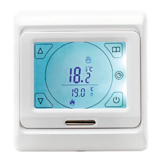
- Page 1 Menu Button Button Clock Button Power Button Down Button Sensor Amber-Touch Complete Guide...
- Page 2 Before programming your Amber-Touch please ensure you read through all these settings carefully. Clock Down Period 1 Power Period 2 Manual Control Period 3 Mode Period 4 Programme Period 5 Mode Indicator Period 6 Menu Screen Heating On Lock For technical information contact: technical@amberufh.co.uk...
-
Page 3: Time And Date Setup
Time & Date Setup With the unit on, simply hold the button until the minutes begin to fl ash (5 seconds) Set the correct time by using the buttons, using the button to switch from minutes to hours and again to edit the day Use the buttons to select the correct day: 1 = Monday, 7 = Sunday... -
Page 4: Sensor Mode
Sensor Mode Having initiated the advanced settings, tap the button to switch to Sensor Mode (2SEN) and set to OUT by using the buttons There are 3 sensor modes available to choose from, Air Sensor Only (IN), Floor Sensor Only (OUT) and Air Sensor with Floor Limit (ALL), you can scroll through these using the buttons. - Page 5 Set Your Ideal Heating Programme With 3 diff erent options available, choose the schedule which best suits your lifestyle. Whether that is all 7 days the same (7day), 5 days and the weekend (5/2), or just 6 days and just 1 separate day (6/1). Having initiated the advanced settings, tap the button...
- Page 6 Create The Perfect Heating Schedule Please note down the scheduled times prior to beginning programming. By default, your Amber-Touch will be set to a 5/2 schedule. To personalise this schedule: Enter schedule mode by pressing button 5 Day Schedule You will see one of the 6 period symbols and the...
-
Page 7: Manual Control
Manual Control If required you may choose to access manual control of your Amber-Touch. You can easily switch between the manual mode and your custom schedule by tapping the button When in manual mode, you will see the manual control mode icon... -
Page 8: Frost Protection
Frost Protection An active frost protection feature will ensure your substrate never falls below 10°C. Helping to reduce the heat up times and protecting the fl oor fi nish from potential damage. Having initiated the advanced settings, tap button continuously until you see the frost protection mode (5LrP) Using the buttons, simply set... -
Page 9: Error Codes
Contact your electrician, who can isolate the electricity supply and check the sensor is connected and working correctly. Screen Lock In some situations where your Amber-Touch is installed into a location where restricted access is necessary, simply: Press and hold the buttons until the appears on the screen. - Page 10 3 Simple Steps to Factory Reset 1. Having initiated the advanced settings, tap the menu button continuously until you see AFAC 2. Hold the button until “---” is displayed on the screen 3. Press the button and switch off at the mains to complete factory reset Please note: the time displayed will not reset and will stay the same prior to factory reset.
-
Page 11: Advanced Settings Overview
Advanced Settings Overview Symbol Setting Default Temperature Adjust measured calibration temperature IN: built-in sensor OUT: floor sensor ALL: both Sensor mode sensors (floor sensor is the limit sensor) Adjust limitation Max floor value, 35°C temperature Limitation range: 5˚C~35˚C Switching Adjust switching differential differential Frost... - Page 12 2: 5/2 day mode Heating 1: 6/1 day mode schedule 0: 7 day mode Output Not Used Change the Output delay delay time Max. Limitation temperature 50°C temperature setting setpoint (50˚C) Programming parameters Reset to will be reset to factory AFAC factory settings settings...
- Page 13 Dimensions 86mm...
-
Page 14: Installation Guide
Installation Guide STEP 1 Release the front cover by inserting screwdriver into the hole on the underside of the front plate... - Page 15 STEP 2 Take the backing plate apart according to diagram STEP 3 Install the backing plate on to the electrical connection box with screws before any wiring takes place...
- Page 16 STEP 4 Ensure all wiring is undertaken by a qualified electrician Max load 16A (3600W) Sensor L1 N1 STEP 5 Install the housing cover and lock external frame as per diagrams...
Need help?
Do you have a question about the Amber-Touch and is the answer not in the manual?
Questions and answers