
Related Manuals for iSMA MINI Series

Summary of Contents for iSMA MINI Series
- Page 1 MINI and MIX Series I/O modules User Manual Modbus Global Control 5 Sp. z o.o. Warsaw, Poland www.gc5.pl Poland, Warsaw www.gc5.pl...
-
Page 2: Table Of Contents
Table of contents Introduction ..............................5 Revision history ..............................5 Safety rules................................6 .Technical specifications ............................ 7 Summary table for all modules ......................... 9 Dimension ................................11 Power supply connection ..........................12 DC power connection..............................12 AC power connection ..............................12 Connecting the communication bus (RS485) ..................... 12 LED Indicators .............................. - Page 3 MINI and MIX Series I/O modules/Modbus Digital Inputs MODBUS Registers ........................27 State of Digital Inputs (30016) .............................27 Counter 1 – 12 (40023, 40024 – 40045, 40046) .....................27 Resetting counters (40022)............................28 Analog Outputs Connections .......................... 28 Connection of Analog Output 0 – 10 V ........................28 Connecting relay to Analog Output ..........................28 Connection an actuator to Analog Output .........................29 Analog Outputs MODBUS Registers ......................
- Page 4 MINI and MIX Series I/O modules/Modbus Module as Modbus TCP/IP Gateway to RS485 ..................51 List of all Modbus Registers ........................53 List of supported temperature sensors ....................62 version 1.3 www.gc5.pl Page 4 / 73...
-
Page 5: Introduction
At 12.2015 GC5 released a new hardware version for MIX module with more • powerful processor and USB port. For this hardware and for all MINI series devices we released firmware 4.0 which contains bug fix, firmware improvement and also rebuilt BACnet protocol (new object, COV). -
Page 6: Safety Rules
MINI and MIX Series I/O modules/Modbus New functions: added Hardware Version information on main tab in web page and Modbus • register new action in the Modbus register no 0 – enter bootloader • added RS485 biasing control for MINI modules with a hardware version >= 2.0 •... -
Page 7: Technical Specifications
MINI and MIX Series I/O modules/Modbus Technical specifications Voltage 24 V AC/DC ± 20% Power consumption Module type @ 24 VDC @ 24 VAC 0.4 W 0.6 VA 8I-IP 1.4 W 2.1 VA 0.5 W 0.8 VA 8U-IP 1.5 W 2.3 VA 4I4O-H 1.2 W... - Page 8 MINI and MIX Series I/O modules/Modbus Resistance measurement method The voltage divider Dry contact input Output current ~1 mA Measurement resolution 12-bits (default) or 16-bits Processing time 10 ms/channel at 12-bits • 140 ms/channel at 16-bits • Type Dry contact Digital Inputs Max input frequency 100 Hz...
-
Page 9: Summary Table For All Modules
Length 88 mm Height 62 mm MIX38, MIX38-IP Width 110 mm Length 160 mm Height 62 mm MINI Series Width 110 mm Length 37 mm Height 62 mm Table 2 Technical specification Summary table for all modules Modbu Module Modbus... - Page 10 MINI and MIX Series I/O modules/Modbus 4TO-H ✓ ✓ ✓ 4TO-H-IP ✓ ✓ ✓ MIX18 ✓ ✓ MIX18-IP ✓ ✓ ✓ MIX38 ✓ ✓ MIX38-IP ✓ ✓ ✓ Modbus Master Gateway ASCII Slave IP/RS485 Table 3 Summary table for all modules version 1.3 www.gc5.pl Page 10 / 73...
-
Page 11: Dimension
MINI and MIX Series I/O modules/Modbus Dimension Figure 1 MINI series dimension Figure 2 MIX18 and MIX18-IP dimension Figure 3 MIX38 and MIX38-IP dimension version 1.3 www.gc5.pl Page 11 / 73... -
Page 12: Power Supply Connection
MINI and MIX Series I/O modules/Modbus Power supply connection DC power connection Figure 4 DC power supply connection AC power connection Figure 5 AC power supply connection Connecting the communication bus (RS485) Figure 6 RS485 connection version 1.3 www.gc5.pl Page 12 / 73... -
Page 13: Led Indicators
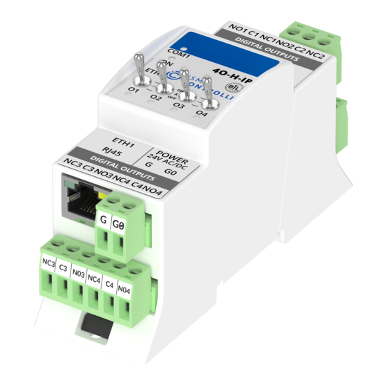
MINI and MIX Series I/O modules/Modbus LED Indicators Figure 7 Top panel MIX18-IP Figure 8 Top panel MIX38-IP Figure 9 Top panel 8I and 8I-IP Figure 10 Top panel 8U and 8U-IP Figure 12 Top panel 4U4O-H and 4U4O-H-IP Figure 11 Top panel 4I4O-H and 4I4O-H-IP Figure 14 Top panel 4O-H and 4O-H-IP Figure 13 Top panel 4U4A-H and 4U4A-H-IP Figure 15 Top panel 4TO-H and 4TO-H-IP... -
Page 14: Grounding And Shielding
MINI and MIX Series I/O modules/Modbus The power LED is ON (green) when the module runs properly. • Communication LED is ON (orange) for 20 ms after sending each message. • If the module receives/sends a lot of messages LED can be lit continuously. LEDs indicate the status of the Universal Inputs are lit when resistance connected to •... -
Page 15: Setting Module Address On Modbus Network
MINI and MIX Series I/O modules/Modbus 1.11 Setting Module Address on Modbus Network To determine the address on the Modbus network, module provides two rotary switches S1 and S2 located on the top panel of the device. It is possible to set the device address from 0 to 99. The formula for setting the address: Address = S2 •... -
Page 16: Protocol Selection
MINI and MIX Series I/O modules/Modbus 1.13 Protocol selection Protocol selection is done by sections 4 and 5 of the S3 switch according to table below: Protocol OFF (0) OFF (0) Modbus RTU OFF (0) ON (1) Modbus ASCII ON (1) OFF (0) BACnet Master ON (1) -
Page 17: Default Settings
MINI and MIX Series I/O modules/Modbus 1.15 Default Settings Out of the box device as well as after restoring default values procedure, has got the following default registers values: Register Name Default Value COUNTER BAUD RATE 76800 (76800 bps) STOP BITS DATA BITS PARITY BITS RESPONSE DELAY... -
Page 18: Configuration Registers
MINI and MIX Series I/O modules/Modbus Configuration registers WARNING! Changing the parameters concerning the transmission configuration (except to registers which value is read from the switch) will only take effect after restarting the unit. Firmware version and module type (30001) In this register are encoded type and firmware version of module. -
Page 19: Baud Rate And Protocol (30003)
MINI and MIX Series I/O modules/Modbus Baud rate and protocol (30003) The register contains information about the baud rate and type of protocol in accordance with the table below. This register reflects the state of the switch S3. Baud rate Protocol Bit 0 Bit 1... -
Page 20: Hardware_Version (30130)
MINI modules with a hardware version >= 2.0 The biasing resistors are useful in case when iSMA modules are connected with a third part devices with the same RS485 bus and communication errors appears on the network. -
Page 21: Data Bits (40138)
MINI and MIX Series I/O modules/Modbus Figure 17 Modbus message frame 2.13 Data bits (40138) Number of data bits transmitted in a single byte is determined according to the following table: Value No of data bits 8 (default) Table 11 Data bits 2.14 Parity bit (40139) Each byte of data being transferred may have additional protection as a parity bit added... - Page 22 MINI and MIX Series I/O modules/Modbus default state. This feature is useful if for some reason there is an interruption in data transmission and for security reasons output states must be set to the appropriate state endanger the safety of persons or property. The default value is 0 seconds which means the watchdog function is disabled.
-
Page 23: Local I/O
MINI and MIX Series I/O modules/Modbus Local I/O Universal Inputs connections Connection of Universal Input to measure voltage 0 – 10V Figure 18 Connection of UI to measure 0-10 VDC for MIX38 and MIX38-IP Connection of Universal Input to measure current 0 – 20 mA Current measurement is realized by voltage measurement and 200 Ω... -
Page 24: Connection Of Universal Input To Measure Temperature
MINI and MIX Series I/O modules/Modbus Connection of Universal Input to measure temperature Figure 20 Connection of UI to measure temperature for MIX18 and MIX18-IP Connection of Universal Input as a Digital Input (Dry Contact) Figure 21 Connection of UI to work as DI for MIX38 and MIX38-IP version 1.3 www.gc5.pl Page 24 / 73... -
Page 25: Universal Inputs Modbus Registers
MINI and MIX Series I/O modules/Modbus Universal Inputs MODBUS Registers Status of Universal Inputs working as Digital Inputs (30017) This 16-bits register contains information about the status of Digital Inputs (dry contact). When the input is shortcut to the ground the corresponding bit value is set to 1 in accordance with the following table: No of bit in register No of Universal Input... -
Page 26: Filter Time Constant Of The Universal Input 1 - 8 (40159 - 40166)
MINI and MIX Series I/O modules/Modbus Register value Description Off resistance measurement (only measuring the voltage, dry contact off) 1 (default) The temperature sensor 10K3A1 NTC B=3975K The temperature sensor 10K4A1 NTC B=3695K The temperature sensor 10K NTC B=3435K Carel The temperature sensor 20K6A1 NTC B=4262K The temperature sensor 2,2K3A1 NTC B=3975K The temperature sensor 3K3A1 NTC B=3975K... -
Page 27: Digital Inputs Connections
MINI and MIX Series I/O modules/Modbus Table 15 Universal inputs resolution for MIX38 and MIX38-IP Digital Inputs Connections Connection of Digital Input (Dry Contact) Figure 22 Connection of DI for MIX38 and MIX38-IP Digital Inputs MODBUS Registers State of Digital Inputs (30016) This 16-bit register contains the status of the Digital Inputs. -
Page 28: Resetting Counters (40022)
MINI and MIX Series I/O modules/Modbus Resetting counters (40022) Setting true value of particular bit of this 16-bit register causes reset (sets to 0) the corresponding counter in accordance with the following table: No of bit in register No of Digital Input …... -
Page 29: Connection An Actuator To Analog Output
MINI and MIX Series I/O modules/Modbus Connection an actuator to Analog Output Figure 25 Connection an actuator to AO Analog Outputs MODBUS Registers State of Analog Outputs working as Digital Outputs (40019) Set/setting true value of particular bit of this 16-bit register causes setting maximum output voltage (10 V) on corresponding output and setting to 0 corresponding register with Analog Output value (40121 –... -
Page 30: Default State Of The Analog Output 1 - 6 (40145 - 40150)
MINI and MIX Series I/O modules/Modbus Bits in register correspond to the following Analog Outputs: No of bit in No of Analog Output register Table 19 Default state of AO working as DO for MIX38 and MIX38-IP Default state of the Analog Output 1 – 6 (40145 – 40150) In these 16-bits registers are stored values in mV of voltage which appear on the Analog Outputs after power on or watchdog reset. -
Page 31: Hand Control Value Of Analog Outputs 1 - 4 (30125 - 20128)
MINI and MIX Series I/O modules/Modbus Hand status of outputs Table 21 AO Hand status bits Value of Hand Status status Description AUTO HAND CONTROL Table 22 AO Hand status value The current value of output in the hand mode determines register 30125 to 30128. Hand control value of Analog Outputs 1 –... -
Page 32: Digital Outputs (Relays) Connections
MINI and MIX Series I/O modules/Modbus Digital Outputs (relays) Connections Connecting the solenoid valve to the Digital Output Figure 26 Connection of solenoid valve to DO for MIX38 and MIX38-IP Connecting a resistive load to the Digital Output Figure 27Connection of resistive load to DO for MIX38 and MIX38-IP Connecting a inductive load to the Digital Output Figure 28 Connection of inductive load to DO for MIX38 and MIX38-IP version 1.3... -
Page 33: Digital Outputs (Relays) Modbus Registers
MINI and MIX Series I/O modules/Modbus Digital Outputs (relays) MODBUS Registers State of Digital Outputs (40018) This 16-bit register contains the state of the Digital Outputs. Set/setting the particular bit in the register enables the corresponding Digital Output according to the following table: No of bit in No of Digital Output register... -
Page 34: Triac Outputs Connections
MINI and MIX Series I/O modules/Modbus Value of Hand Status status Description AUTO HAND OUT = 0 HAND OUT = 1 Table 26 DO Hand status value Triac Outputs Connections Connecting the solenoid valve to the Triac Output Figure 28 Connection of solenoid valve to TO for 4TO-H and 4TO-H-IP Connecting a resistive load to the Triac Output Figure 29 Connection of resistive load to TO for 4TO-H and 4TO-H-IP version 1.3... -
Page 35: Triac Outputs Modbus Registers
MINI and MIX Series I/O modules/Modbus 3.10 Triac Outputs MODBUS Registers State of Triac Outputs (40018) This 16-bit register contains the state of the Triac Outputs in digital mode. /Setting particular bit in the register enables the corresponding Triac Output according to the following table: No of bit in No of Triac Output... -
Page 36: Hand Control Status Of Triac Outputs (30015)
MINI and MIX Series I/O modules/Modbus Register Description value 1 (default) Digital Output PWM 1Hz PWM 10Hz Not supported PWM 0.1 HZ PWM 0.01Hz Table 29 TO type settings Hand control status of Triac Outputs (30015) This register is available only for the modules with manual control of outputs. No of bit in Description register... -
Page 37: Special Application Modes For 4I4O-H, 4I4O-H-Ip, 4U4O-H And 4U4O-H-Ip
MINI and MIX Series I/O modules/Modbus 3.11 Special application modes for 4I4O-H, 4I4O-H-IP, 4U4O-H and 4U4O- H-IP In 4I4O-H, 4I4O-H-IP, 4U4O-H, 4U4O-H-IP modules simple applications have been built which can be used to control building devices. The applications make logic between signal from Digital Input and control Digital Output state. -
Page 38: Operation Mode Registers (40176,40180,40184,40188)
MINI and MIX Series I/O modules/Modbus 40190 DI4 SETPOINT (4U4O-H and 4U4O-H-IP only) 40191 DI4 DIFFERENTIAL (4U4O-H and 4U4O-H-IP only) Table 33 List of registers dedicated for special application mode Operation Mode registers (40176,40180,40184,40188) This register contains information about module working mode. Available modes and register values are shown in the table below: Value OPERATION MODE Register... - Page 39 MINI and MIX Series I/O modules/Modbus 3.11.1.3 Bistabile Relay In this mode only rising edge on digital input change output state. The action of bistable relay can by executed remotely by changing the state of bit from false to true in COMMAND register (40020).
- Page 40 MINI and MIX Series I/O modules/Modbus 3.11.1.8 Input Forwarding In this mode, any signal from the input is transferred directly to the assigned output without any modifications. The input forwarding mode functioning can be stopped by Block Input function (see Block Inputs register).
-
Page 41: Time Value Registers (40177,40181,40185,40189)
MINI and MIX Series I/O modules/Modbus 3.11.1.10 Cooling mode (4U4O-H and 4U4O-H-IP only) In this mode output is controlled as a typical thermostat, based on Setpoint register and Control value (Input signal) with differential parameter defined in Differential register. The output signal works in 2 states - low and high. When Control value is lower or equal the difference of Setpoint register and Differential register the output is in low state. -
Page 42: Command Register (40020)
MINI and MIX Series I/O modules/Modbus Command register (40020) The module have special register COMMAND (40020). The command register is used for remotely execute action ( simulate light switch/PIR). The action is executed by changing state of relevant bit (changing from false to true). All special application modes can be executed except Input Forwarding, Heating and Cooling modes. -
Page 43: Web Configuration- Only Ip Version
MINI and MIX Series I/O modules/Modbus The default Differential value is 1. (read more in Heating mode, Cooling mode). The register stores the differential multiplied by 10. WEB Configuration- only IP version Web server access All IP version modules have built in web server, which allows to show module status and to change configuration. -
Page 44: Local I/O Status And Configuration
MINI and MIX Series I/O modules/Modbus Local I/O status and configuration Universal Inputs This page allows to enter configuration parameters and show actual value of Universal Inputs. To open this page please navigate to Local IO tab and choose Universal Inputs from submenu. -
Page 45: Special Application Modes Configuration
MINI and MIX Series I/O modules/Modbus • Temperature (Read Only), in Celsius with an accuracy of 1 decimal [°C]. • Voltage (Read Only) in millivolts [mV]. WARNING! To save changes please use “Submit” button Special application modes configuration This page allows to enter configuration parameters and show actual value of Special application modes. -
Page 46: Digital Inputs
MINI and MIX Series I/O modules/Modbus In default 0. • Differential (Read & Write, 4U4O-H-IP only), differential value for heating/cooling modes. In default 0. WARNING! To save changes please use “Submit” button Digital Inputs This page allows to enter configuration parameters and shows actual value of Digital Inputs. -
Page 47: Analog Outputs
MINI and MIX Series I/O modules/Modbus Figure 38 Digital Outputs page of MIX38-IP Digital Outputs table has the following fields: • State (Read & Write), actual state of digital output. • Default State (Read & Write), output state after power up and watchdog. •... -
Page 48: Rs485 Configuration
MINI and MIX Series I/O modules/Modbus • Hand State Output (Read Only, MINI series only), manual overrides potentiometer status WARNING! To save changes please use “Submit” button RS485 Configuration This page allow to enter configuration parameters and show information of controllers RS485 port. -
Page 49: Ip Configuration
MINI and MIX Series I/O modules/Modbus IP Configuration This page allows to change parameters of Ethernet port, Modbus TCP and BACnet IP. Figure 41 IP configuration page This page allows to set parameters such as: • IP Address (Read & Write), controller Ethernet interface IP address. •... -
Page 50: Device Management
MINI and MIX Series I/O modules/Modbus Device management This page allows to change password and remote reboot device. Figure 42 Device management page Procedure of changing device password: a) enter current device password in field - Current Device Password, b) enter new device password in field - New Device Password, c) enter again new device password in field - Confirm New Device Password, d) to confirm password change please click “Submit”... -
Page 51: Modbus Tcp/Ip Modules
No retry may result in immediate going point to down mode. That is why modules have the ability to block the sending information about errors (Send Modbus Errors setting from built in web or iSMA-Configurator). Then in the absence of any response, the system retry the request according to the settings. - Page 52 MINI and MIX Series I/O modules/Modbus Figure 44 Modbus TCP/IP to RS485 Gateway an example version 1.3 www.gc5.pl Page 52 / 73...
- Page 53 (32 – bits) parameters. STATUS OF MANUAL Status of manual operation DO, TO and 30015 Read Only OPERATION AO for modules MINI series 30016 0x0F STATE OF DIGITAL INPUTS Read Only STATE OF UNIVERSAL INPUTS Status of Universal Inputs working as...
- Page 54 MINI and MIX Series I/O modules/Modbus Modbus Register name Access Description Addr Addr Addr Write counter. 40023 0x16 COUNTER 1 LSB Read & Write 40024 0x17 COUNTER 1 MSB Memory 40025 0x18 COUNTER 2 LSB Read & Write 40026 0x19 COUNTER 2 MSB Memory 40027...
- Page 55 MINI and MIX Series I/O modules/Modbus Modbus Register name Access Description Addr Addr Addr UIVERSAL INPUT VOLTAGE Formula for the current measurements: 30073 0x48 Read Only �� �� = UIVERSAL INPUT where: U – register value, 30074 0x49 Read Only TEMPERATURE 2 500 –...
- Page 56 MINI and MIX Series I/O modules/Modbus Modbus Register name Access Description Addr Addr Addr UIVERSAL INPUT VOLTAGE 30094 0x5D Read Only UIVERSAL INPUT 30095 0x5E Read Only TEMPERATURE 1 UIVERSAL INPUT 30096 0x5F Read Only TEMPERATURE 2 UIVERSAL INPUT 30097 0x60 Read Only TEMPERATURE 3...
- Page 57 MINI and MIX Series I/O modules/Modbus Modbus Register name Access Description Addr Addr Addr OUTPUT 2 Write in the mV range from 0 to 10000mV VALUE OF ANALOG Read & 40123 0x7A OUTPUT 3 Write VALUE OF ANALOG Read & 40124 0x7B OUTPUT 4...
- Page 58 MINI and MIX Series I/O modules/Modbus Modbus Register name Access Description Addr Addr Addr Memory Time in second before watchdog reset Read & in case no transmission. 40141 0x8C WATCHDOG TIME Write A value of 0 disables Watchdog. Memory The default value is 0s Read &...
- Page 59 MINI and MIX Series I/O modules/Modbus Modbus Register name Access Description Addr Addr Addr CONFIGURATION 5 Write 20K6A1 NTC Memory 2,2K3A1 NTC B=3975K Read & UNIVERSAL INPUT 3K3A1 NTC 40156 0x9B Write CONFIGURATION 6 Memory 30K6A1 NTC Read & SIE1 UNIVERSAL INPUT 40157 0x9C...
- Page 60 MINI and MIX Series I/O modules/Modbus Modbus Register name Access Description Addr Addr Addr with 12-bit resolution. Read & ANALOG OUTPUT 40168 0xA7 Write CONFIGURATION 1 Memory Read & Configuring the mode of Analog Output ANALOG OUTPUT 40169 0xA8 Write according to the following table: CONFIGURATION 2 Memory...
- Page 61 MINI and MIX Series I/O modules/Modbus Modbus Register name Access Description Addr Addr Addr Read & DIGITAL INPUT 3 40184 0xB7 Write DIFFERENTIAL in C multiplied by 10 CONFIGURATIO MODE Memory Default value = 0 Read & DIGITAL INPUT 3 40185 0XB8 Write...
- Page 62 MINI and MIX Series I/O modules/Modbus List of supported temperature sensors Sensor 10K3A1 Sensor 10K4A1 β coeffictient 3975K β coeffictient 3695K Aquatrol, Cylon, Honeywell, Andover, Delta Manufacturers Johnson, Satchwell, Manufacturers Controls, Siebe, York Seachange °C Ω °C Ω 667828 441667 491749 330749 335671...
- Page 63 MINI and MIX Series I/O modules/Modbus 1084 version 1.3 www.gc5.pl Page 63 / 73...
- Page 64 MINI and MIX Series I/O modules/Modbus Sensor 10K Carel Sensor 20K6A1 β coeffictient 3435K β coeffictient 4262K °C Ω Manufacturers Honeywell 329500 °C Ω 247700 806800 188500 574400 144100 413400 111300 300400 86430 220600 67770 163480 53410 122260 42470 92220 33900 70140 27280...
- Page 65 MINI and MIX Series I/O modules/Modbus version 1.3 www.gc5.pl Page 65 / 73...
- Page 66 MINI and MIX Series I/O modules/Modbus Sensor 2.2K3A1 Sensor 3K3A1 β coeffictient 3975K β coeffictient 3975K Manufacturers Manufacturers Ambiflex, Johnson Alerton °C Ω °C Ω 329500 200348 247700 150524 188500 100701 144100 76853 111300 53005 86430 41048 67770 29092 53410 21868 42470 16589...
- Page 67 MINI and MIX Series I/O modules/Modbus version 1.3 www.gc5.pl Page 67 / 73...
- Page 68 MINI and MIX Series I/O modules/Modbus Sensor 30K6A1 Sensor SIE1 β coeffictient 4262K Manufacturers Barber Colman, Siebe Manufacturers °C Ω Drayton 10732 °C Ω 622911 10624 477393 10517 331876 10344 245785 10172 183697 9913 138502 9654 105305 9320 60713 8933 62347 8496 48511...
- Page 69 MINI and MIX Series I/O modules/Modbus version 1.3 www.gc5.pl Page 69 / 73...
- Page 70 MINI and MIX Series I/O modules/Modbus Sensor TAC1 Sensor SAT1 β coeffictient 3500K Manufacturers Satchwell Manufacturers °C Ω 9719 °C Ω 39024 9652 29358 9584 22284 9467 17073 9349 13192 9159 10276 8968 8068 8708 6382 8396 5085 8031 4078 7614 3294 7150...
- Page 71 MINI and MIX Series I/O modules/Modbus version 1.3 www.gc5.pl Page 71 / 73...
- Page 72 MINI and MIX Series I/O modules/Modbus Sensor Pt1000 Sensor Pt1000 Honeywell, Sauter, Serck, Honeywell, Sauter, Manufacturers Manufacturers Siebe, Cylon Serck, Siebe, Cylon °C Ω °C Ω 803,1 2156,1 842,7 2191,5 882,2 2226,8 921,6 2262,1 960,9 2297,2 1000,0 2332,1 1039,0 2367,0 1077,9 2401,8 1116,7...
- Page 73 MINI and MIX Series I/O modules/Modbus 1977,1 1687,9 2013,1 1759,8 2049,0 1833,4 2084,8 1909,0 2120,5 1986,6 version 1.3 www.gc5.pl Page 73 / 73...
Need help?
Do you have a question about the MINI Series and is the answer not in the manual?
Questions and answers