
Related Manuals for iSMA iSMA-B-MINI Series

Summary of Contents for iSMA iSMA-B-MINI Series
- Page 1 User Manual Modbus www.ismacontrolli.com DMP262en | 1st Issue rev. 8 | 05/2022...
-
Page 2: Table Of Contents
Modbus User Manual Table of Contents Introduction ..........................6 Revision History..........................7 Safety Rules..........................9 Wiring............................... 10 EN 60730-1 Power Supply Considerations ................10 FCC Compliance Note........................10 Technical Specification ......................12 Summary Table for All Modules ....................15 Hardware Specification ....................... 17 Dimensions ............................ - Page 3 Modbus User Manual 5.4.1 Analog Output Voltage Connection ................... 29 5.4.2 Analog Output Relay Connection ..................30 5.4.3 Analog Output Actuator Connection ................. 30 Digital Outputs ..........................30 5.5.1 Digital Output Solenoid Valve Connection ............... 31 5.5.2 Digital Output Resistive Load Connection................ 31 5.5.3...
- Page 4 Modbus User Manual 7.2.1 State of Digital Inputs (30016) ..................... 41 7.2.2 Counter 1-12 (40023, 40024-40045, 40046)..............41 7.2.3 Resetting the Counters (40022) ..................41 Analog Output Registers......................42 7.3.1 State of Analog Outputs Operating as Digital Outputs (40019)........42 7.3.2...
- Page 5 Modbus User Manual 8.3.4 Analog Outputs ........................58 RS485 Configuration........................59 IP Configuration ..........................59 Device Management ........................60 Contact ............................61 List of Modbus Registers ....................62 List of Supported Temperature Sensors ................ 73 www.ismacontrolli.com DMP262en | 1st Issue rev. 8 | 05/2022...
-
Page 6: Introduction
Modbus User Manual 1 Introduction The MINI and MIX series of I/O modules with RS485 and IP (2 Ethernet) have been designed for building distributed control systems using MAC36, AAC20, or another controller. Each module is equipped with the most commonly used types of I/O in building automation. -
Page 7: Revision History
Modbus User Manual 1.1 Revision History Rev. Date Description 28 Aug 2015 First edition 1 Feb 2016 • Information about the capacitive load relay added to the technical specifications. • Information about load Triac Outputs added to the technical specifications. - Page 8 Modbus User Manual Rev. Date Description • fixed overridden flags in AO, BO and TO • fixed bug with number of counters for Binary input object (now variable is 32 bit) • changed AO-1, BO-1, TO-1 HAND_STATUS Access to read- only •...
-
Page 9: Safety Rules
Modbus User Manual 2 Safety Rules • Improper wiring of the product can damage it and lead to other hazards. Make sure that the product has been correctly wired before turning the power on. • Before wiring or removing/mounting the product, make sure to turn the power off. -
Page 10: Wiring
Whether or not the iSMA modules are immune to such effects, the interferences must be suppressed at their source if possible to ensure the proper functioning of the entire system. - Page 11 Modbus User Manual particular installation. If this equipment does cause harmful interference to radio or television reception, which can be determined by turning the equipment off and on, the user is encouraged to try to correct the interference by one or more of the following measures: •...
-
Page 12: Technical Specification
Modbus User Manual 3 Technical Specification Power supply Voltage 24 V AC/DC ± 20% Power consumption Module type At 24 V DC At 24 V AC 0.4 W 0.6 VA 8I-IP 1.4 W 2.1 VA 0.5 W 0.8 VA 8U-IP 1.5 W... - Page 13 Modbus User Manual Current input Current measurement in 0 - 20 mA range Required external resistor 200 Ω Measurement accuracy ±1.1% Measurement resolution 15 µA at 12-bit and 5 µA at 16- Resistive input Measurement of resistance in 0 to 1000 kΩ range Measurement resolution for 20 kΩ...
- Page 14 Modbus User Manual Digital Outputs Contact material AgSnO2 (relays) UL compliant ratings Maximum ratings 4O-H and 4O-H-IP Resistive load AC1 8 A at 230 V AC 8 A at 230 V AC 8 A at 30 V DC...
-
Page 15: Summary Table For All Modules
Modbus User Manual Humidity Relative 5% to 95% Connectors Type Removable Maximum cable size 2.5 mm (18 – 12 AWG) Maximum tightening torque 0,35 Nm Dimensions MIX18, MIX18-IP Width 110 mm (4.331 in) Length 88 mm (3.4646 in) Height 62 mm (2.441 in) - Page 16 Modbus User Manual 4U4O-H 4U4O-H- 8I-IP 8U-IP 4TO-H ...
-
Page 17: Hardware Specification
Modbus User Manual 4 Hardware Specification 4.1 Dimensions 4.1.1 MINI Series Dimensions Figure 2. The MINI series dimensions 4.1.2 MIX18 Series Dimensions Figure 3. The MIX18 series dimensions 4.1.3 MIX38 Series Dimensions Figure 4. The MIX38 series dimensions www.ismacontrolli.com DMP262en | 1st Issue rev. -
Page 18: Power Supply Connection
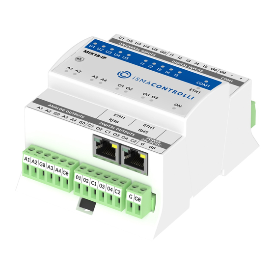
Modbus User Manual 4.2 Power Supply Connection Figure 5. AC power supply connection Figure 6. DC power supply connection 4.3 LED Indicators 4.3.1 MIX Series Front Panels MIX18 Top Panels Figure 7. The MIX18 top panel Figure 8. The MIX18-IP top panel www.ismacontrolli.com... -
Page 19: Mini Series Front Panels
Modbus User Manual MIX38 Top Panels Figure 9. The MIX38 top panel Figure 10. The MIX38-IP top panel 4.3.2 MINI Series Front Panels MINI 8I and 8I-IP Top Panels Figure 11. The 8I top panel Figure 12. The 8I-IP top panel MINI 8U and 8U-IP Top Panels Figure 13. - Page 20 Modbus User Manual MINI 4I4O-H and 4I4O-H-IP Top Panels Figure 15. The 4I4O-H top panel Figure 16. The 4I4O-H-IP top panel MINI 4U4O-H and 4U4O-H-IP Top Panels Figure 17. The 4U4O-H top panel Figure 18. The 4U4O-H-IP top panel MINI 4U4A-H and 4U4A-H-IP Top Panels Figure 19.
- Page 21 Modbus User Manual MINI 4O-H and 4O-H-IP Top Panels Figure 21. The 4O-H top panel Figure 22. The 4O-H-IP top panel MINI 4TO-H and 4TO-H-IP Top Panels Figure 23. The 4TO-H top panel Figure 24. The 4TO-H-IP top panel •...
-
Page 22: Rs485 Port
Modbus User Manual 4.4 RS485 Port 4.4.1 RS485 Communication Bus Connection Figure 25. RS485 connection 4.4.2 RS485 Network Termination Transmission line effects often present problems for data communication networks. These problems include reflections and signal attenuation. To eliminate the presence of reflections of signal from the end of the cable, the cable must be terminated at both ends with a resistor across the line adequate to its characteristic impedance. -
Page 23: Baud Rate
Modbus User Manual Switches set as in the figure above will set the module address to 11. 4.6 Baud Rate The transmission baud rate is set with the S3 switch (sections 1, 2, and 3) in accordance with the following table:... - Page 24 Modbus User Manual USER BAUD RATE 7680 (76800 bps) STOP BITS DATA BITS PARITY BITS RESPONSE DELAY WATCHDOG TIME 0 (disabled) STATE OF THE DIGITAL OUTPUTS AFTER START STATE OF THE ANALOG OUTPUTS (DIGITAL) AFTER START STATE OF THE ANALOG OUTPUTS AFTER START...
-
Page 25: Restoring Default Settings
Modbus User Manual 4.8.1 Restoring Default Settings To restore the default configuration of all registers, follow the steps below: • turn off the power supply; • set section 6 of the S3 switch to on; • turn on the power supply, the power LED will start blinking;... -
Page 26: Inputs And Outputs
5 Inputs and Outputs 5.1 Local I/O The iSMA-B-MINI/MIX modules are equipped with local inputs and outputs (universal inputs, digital inputs, analog outputs, digital outputs, and triac outputs), and their quantities differ between the modules types, according to the table:... -
Page 27: Universal Input Voltage Connection
Modbus User Manual • resistance and temperature measurement (10k thermistor, a full list of supported temperature sensors is available here: List of Supported Temperature Sensors); • dry contact (output current 1 mA). Current measurement is realized by voltage measurement and 200 Ω resistance. -
Page 28: Universal Input Resistance Connection
Modbus User Manual 5.2.3 Universal Input Resistance Connection Figure 29. A universal input resistance connection 5.2.4 Universal Input Dry Contact Connection Figure 30. A universal input dry contact connection 5.3 Digital Inputs Digital inputs operate as standard dry contact inputs and, additionally, as high speed pulse counters up to 100 Hz. -
Page 29: Digital Input Counter
Modbus User Manual Figure 31. A digital input connection 5.3.1 Digital Input Counter A digital input can work as a counter of dry contact pulses up to 100 Hz. The connection is identical as in case of the dry contact input. -
Page 30: Analog Output Relay Connection
Modbus User Manual 5.4.2 Analog Output Relay Connection Figure 33. An analog output relay connection 5.4.3 Analog Output Actuator Connection Figure 34. An analog output actuator connection 5.5 Digital Outputs Digital outputs operate as relay outputs with maximum loads of: •... -
Page 31: Digital Output Solenoid Valve Connection
Modbus User Manual 5.5.1 Digital Output Solenoid Valve Connection Figure 35. A digital output solenoid valve connection 5.5.2 Digital Output Resistive Load Connection Figure 36. A digital output resistive load connection 5.5.3 Digital Output Inductive Load Connection Figure 37. A digital output inductive load connection www.ismacontrolli.com... -
Page 32: Triac Outputs
Modbus User Manual 5.6 Triac Outputs Triac outputs work as typical binary outputs or in Pulse Width Modulation (PWM) mode: 0,01 Hz, 0,1 Hz, 1 Hz, 10 Hz. Figure 38. A triac output connection www.ismacontrolli.com DMP262en | 1st Issue rev. 8 | 05/2022... -
Page 33: Configuration Registers
Modbus User Manual 6 Configuration Registers WARNING! Changing the configuration parameters of the transmission will only take effect after restarting the unit (except for the registers the value of which is read from the switch). 6.1 Firmware Version and Module Type (30001) In this register type and firmware version of the module are encoded. -
Page 34: Module Address (30002)
Modbus User Manual The high byte contains the module firmware version multiplied by 10. For example: In the 30001 register, number 12810 = 0x320A , which means that it is module MIX18 (0x32) with firmware in version 1.0 (0x0A = 10 6.2 Module Address (30002) -
Page 35: Counter Of Sent Messages (30008)
Modbus User Manual 6.6 Counter of Sent Messages (30008) The 32-bit register with the number of error Modbus messages received by the module, which was powered up last. The value is reset after the power cycle or after changing transmission parameters (speed, stop bits, parity, etc.). -
Page 36: Data Bits (40138)
If the bit no. 8 is true (bit 8 = 1), RS485 biasing resistors are activated. The function is only available in MINI IP I/O modules with hardware version >= 2.0 The biasing resistors are useful in case the iSMA modules are connected with third-party devices with the same RS485 bus and communication errors appear on the network. -
Page 37: Response Delay Time (40140)
Modbus User Manual Register Value Type of Parity Bit Always 1 Always 0 Table 13. Parity bit 6.15 Response Delay Time (40140) The value of this 16-bit register determines the number of milliseconds to wait before the unit answers the question. This time is used to extend the interval between the question and answer. -
Page 38: Localio Registers
Modbus User Manual 7 LocalIO Registers The following sections describe the BACnet objects dedicated to inputs and outputs of the iSMA-B-MINI/MIX modules. 7.1 Universal Input Registers 7.1.1 Status of Universal Inputs Working as Digital Inputs (30017) This 16-bit register contains information about the status of digital inputs (dry contacts). If... -
Page 39: Universal Input Resistance Measurement 1-8 (30103, 30104-30117, 30118)
Modbus User Manual 7.1.4 Universal Input Resistance Measurement 1-8 (30103, 30104-30117, 30118) In these 16-bit registers the result is expressed in Ω or in 0.1 Ω units for PT1000 and NI1000 configuration. In the register with the lower number, it is the lower storage part of the result and the higher register storage part of the result. -
Page 40: Filter Time Constant Of The Universal Input 1-8 (40159-40166)
Modbus User Manual Register Value Description NI1000 32F (ºF) NI1000 70F (ºF) +128 Off voltage measurement (set 7. bit of register) Table 15. UI configuration 7.1.6 Filter Time Constant of the Universal Input 1-8 (40159-40166) These 16-bit registers contain a time constant low pass filter. The value is expressed in seconds. -
Page 41: Digital Input Registers
Modbus User Manual 7.2 Digital Input Registers 7.2.1 State of Digital Inputs (30016) This 16-bit register contains the status of digital inputs. Short-circuit input to GND sets the corresponding bit in the register in accordance with the table below: No. -
Page 42: Analog Output Registers
Modbus User Manual 7.3 Analog Output Registers 7.3.1 State of Analog Outputs Operating as Digital Outputs (40019) Setting a true value of a particular bit of this 16-bit register causes setting the maximum output voltage (10 V) on the corresponding output and setting the corresponding register with analog output value (40121-40126) to 0. -
Page 43: Default State Of 1-6 Analog Outputs (40145-40150)
Modbus User Manual 7.3.4 Default State of 1-6 Analog Outputs (40145-40150) These 16-bit registers contain the values of voltage in mV, which appear on the analog outputs after turning the power on or resetting the watchdog. 7.3.5 Configuration Mode of 1-6 Analog Outputs (40168-40173) -
Page 44: Digital Output Registers
Modbus User Manual 7.4 Digital Output Registers 7.4.1 State of Digital Outputs (40018) This 16-bit register contains the state of digital outputs. Setting a particular bit in the register activates the corresponding digital output according to the following table: No. -
Page 45: Triac Output Registers
Modbus User Manual No. of Bit in the Register Description 2, 3 Hand status of output 2 4, 5 Hand status of output 3 6, 7 Hand status of output 4 Table 26. DO hand status bits Value of Hand Status... -
Page 46: Value Of 1-4 Triac Pwm Outputs (40121-40124)
Modbus User Manual No. of Bit in the Register No. of Digital Output Table 29. Default state for 4TO-H and 4TO-H-IP 7.5.3 Value of 1-4 Triac PWM Outputs (40121-40124) These 16-bit registers contain the value of the duty that appears on the PWM output (expressed in percents). -
Page 47: Special Application Modes
Modbus User Manual No. of Bit in the Register Description Hand status of outputs 4 Table 31. TO hand status bits Value of Hand Status Status Description AUTO HAND OUT = 0 HAND OUT = 1 Table 32. TO hand status value 7.6 Special Application Modes... -
Page 48: Operation Mode Registers (40176, 40180, 40184, And 40188)
Modbus User Manual Register Description 40179 DI1 DIFFERENTIAL (4U4O-H and 4U4O-H-IP only) 40180 DI2 OPERATION MODE 40181 DI2 TIME VALUE 40182 DI2 SETPOINT (4U4O-H and 4U4O-H-IP only) 40183 DI2 DIFFERENTIAL (4U4O-H and 4U4O-H-IP only) 40184 DI3 OPERATION MODE 40185... - Page 49 Modbus User Manual Value OPERATION MODE Register Time Relay NO [s] Time Relay NC [s] Input Forwarding Heating (4U4O-H and 4U4O-H-IP only) Cooling (4U4O-H and 4U4O-H-IP only) Table 35. Special application modes The operating mode can be changed by writing the right value in the Operation Mode register.
- Page 50 Modbus User Manual Time Relay NC [ms] In this mode, if the output value is false, the falling edge of the digital input sets the output to a true value. Every rising edge of the digital input starts the counter from the beginning so that the output stays in true value for a time defined in the TIME VALUE register (expressed in milliseconds), counting from the last rising edge of the digital input.
- Page 51 Modbus User Manual The algorithm of the heating mode is shown in chart below. Figure 40. The heating mode algorithm WARNING! In case when the temperature sensor fails (when it is disconnected or shortcut), the heating mode is not active and the output remains in the false state.
-
Page 52: Time Value Registers (40177,40181,40185,40189)
Modbus User Manual Figure 41. The cooling mode algorithm WARNING! In case when the temperature sensor fails (if it is disconnected or shortcut), the heating mode does not work and the output remains in the false state. 7.6.3 Time Value Registers (40177,40181,40185,40189) The registers contain time values for TIME RELAY modes. -
Page 53: Setpoint Registers (40178, 40182, 40186, 40190)
Modbus User Manual be executed. Setting false value restores normal operation. The block input function does not work when the heating/cooling input mode is set. No. of Bit in the Register (40021) Block Input Number Table 37. Block input register 7.6.6 Setpoint Registers (40178, 40182, 40186, 40190) -
Page 54: Web Configuration
Modbus User Manual 8 Web Configuration This section outlines all information specific to configuring IP modules in a web server. WARNING! Please note that web configuration features are available only for IP versions for the MINI/MIX modules. 8.1 Web Server Access All IP version modules are equipped with a built-in web server, which allows for showing the status of the module and for changing the configuration. -
Page 55: Localio Status And Configuration
Modbus User Manual 8.3 LocalIO Status and Configuration 8.3.1 Universal Inputs This page allows for entering the configuration parameters and showing the actual value of the universal inputs. To open this page, please navigate to the Local I/O tab and choose Universal Inputs from the submenu. - Page 56 Modbus User Manual WARNING! To save changes, please use the “Submit” button. Configuration of Special Application Modes This page allows for entering the configuration parameters and showing the actual value of Special application modes. To open this page, please navigate to the Local I/O tab and choose Universal Inputs from the submenu.
-
Page 57: Digital Inputs
Modbus User Manual WARNING! To save changes, please use the “Submit” button. 8.3.2 Digital Inputs This page allows for entering the configuration parameters and showing the actual value of the digital inputs. To open this page, please navigate to the Local IO tab and choose Digital Inputs from the submenu. -
Page 58: Analog Outputs
Modbus User Manual Figure 48. The MIX38-IP Digital Outputs page The Digital Output table contains the following fields: • State (read/write): the actual state of the digital output; • Default State (read/write): the output state after power-up and watchdog operation;... -
Page 59: Rs485 Configuration
Modbus User Manual • Hand State Output (read-only, MINI series only): manually overrides the status of the potentiometer; • BACnet COV Increment (read/write): change of the state sending threshold value. WARNING! To save changes, please use the “Submit” button. 8.4 RS485 Configuration This page allows to enter the configuration parameters and show the information of the controller’s RS485 port. -
Page 60: Device Management
Modbus User Manual Figure 51. The IP configuration page This page allows for setting parameters such as: • IP Address (read/write): the IP address of the controller’s Ethernet interface; • Mask (read/write): the network mask; • Gateway (read/write): the network default gateway;... -
Page 61: Contact
Modbus User Manual Figure 52. The Device Management page The procedure of changing the device password: • enter current device password in the Current Device Password field; • enter the new device password in the New Device Password field;... -
Page 62: List Of Modbus Registers
Modbus User Manual 9 List of Modbus Registers Modbus Decimal Register Name Access Description Address Address Address 30001 0x00 VERSION AND Read-only MODULE TYPE 30002 0x01 MODULE ADDRESS Read-only (state of switch) 30003 0x02 BAUD RATE AND Read-only ... - Page 63 Modbus User Manual Modbus Decimal Register Name Access Description Address Address Address 40019 0x12 STATE OF ANALOG Read/write State of analog outputs OUTPUTS operating as digital outputs WORKING AS DIGITAL OUTPUTS 40020 0x13 DIGITAL INPUTS Read/write Digital inputs command...
- Page 64 Modbus User Manual Modbus Decimal Register Name Access Description Address Address Address 40041 0x28 COUNTER 10 LSB Read/write Memory 40042 0x29 COUNTER 10 MSB 40043 0x2A COUNTER 11 LSB Read/write Memory 40044 0x2B COUNTER 11 MSB 40045 0x2C COUNTER 12 LSB...
- Page 65 Modbus User Manual Modbus Decimal Register Name Access Description Address Address Address 30085 0x54 UIVERSAL INPUT Read-only VOLTAGE 8 30086 0x55 UIVERSAL INPUT Read-only TEMPERATURE 8 30087 0x56 UIVERSAL INPUT Read-only VOLTAGE 1 30088 0x57 UIVERSAL INPUT Read-only VOLTAGE 2...
- Page 66 Modbus User Manual Modbus Decimal Register Name Access Description Address Address Address 30103 0x66 RESISTIVE INPUT 1 Read-only Resistance measurement result expressed in Ω 30104 0x67 RESISTIVE INPUT 1 Read-only 30105 0x68 RESISTIVE INPUT 2 Read-only 30106 0x69 RESISTIVE INPUT 2...
- Page 67 Modbus User Manual Modbus Decimal Register Name Access Description Address Address Address 40123 0x7A VALUE OF ANALOG Read/write OUTPUT 3 40124 0x7B VALUE OF ANALOG Read/write OUTPUT 4 40125 0x7C VALUE OF ANALOG Read/write OUTPUT 5 40126 0x7D VALUE OF ANALOG...
- Page 68 Modbus User Manual Modbus Decimal Register Name Access Description Address Address Address Value Descripti 0 (default) None Even Always 1 Always 0 40140 0x8B RESPONSE DELAY Read/write Delay in ms before sending the response Memory The default value is 0...
- Page 69 Modbus User Manual Modbus Decimal Register Name Access Description Address Address Address 40150 0x95 DEFAULT STATE OF Read/write ANALOG OUTPUT 6 Memory 40151 0x96 UNIVERSAL INPUT Read/write Configuration of universal CONFIGURATION 1 input and type of Memory temperature sensor...
- Page 70 Modbus User Manual Modbus Decimal Register Name Access Description Address Address Address 40160 0x9F FILTER TIME Read/write CONSTANT Memory OF THE UNIVERSAL INPUT 2 40161 0xA0 FILTER TIME Read/write CONSTANT Memory OF THE UNIVERSAL INPUT 3 40162 0xA1 FILTER TIME...
- Page 71 Modbus User Manual Modbus Decimal Register Name Access Description Address Address Address 40169 0xA8 ANALOG OUTPUT Read/write Value Descriptio CONFIGURATION 2 Memory Voltage 40170 0xA9 ANALOG OUTPUT Read/write (default) output 0‑10 CONFIGURATION 3 Memory 40171 0xAA ANALOG OUTPUT Read/write...
- Page 72 Modbus User Manual Modbus Decimal Register Name Access Description Address Address Address 40177 0xB0 DIGITAL INPUT 1 Read/write Valu OPERATING MODE TIME VALUE Memory Cooling 40178 0xB1 DIGITAL INPUT 1 Read/write (4U4O-H and SETPOINT Memory 4U4O-H-IP only) 40179 0xB2...
-
Page 73: List Of Supported Temperature Sensors
Modbus User Manual 10 List of Supported Temperature Sensors • 10K3A1 • 10K4A1 • 10K Carel • 20K6A1 • 2.2K3A1 • 3K3A1 • 30K6A1 • SIE1 • TAC1 • SAT1 • PT1000 • NI1000 • NI1000 21C (ºC) •... - Page 74 Modbus User Manual 42314 32650 25396 19904 15714 12494 10000 8056 6530 5325 4367 3601 2985 2487 2082 1751 1480 1256 1070 www.ismacontrolli.com DMP262en | 1st Issue rev. 8 | 05/2022 page 74 of 107...
- Page 75 Modbus User Manual 10K4A1 Sensor β coefficient 3695K Manufacturers Andover, Delta Controls, Siebe, York °C Ω 441667 330749 239831 181532 135233 105081 78930 61030 47549 37316 29490 23462 18787 15136 12268 10000 8197 6754 5594 4656 www.ismacontrolli.com DMP262en | 1st Issue rev. 8 | 05/2022...
- Page 76 Modbus User Manual 3893 3271 2760 2339 1990 1700 1458 1255 1084 Sensor 10K Carel β coefficient 3435K °C Ω 329500 247700 188500 144100 111300 86430 www.ismacontrolli.com DMP262en | 1st Issue rev. 8 | 05/2022 page 76 of 107...
- Page 77 Modbus User Manual 67770 53410 42470 33900 27280 22050 17960 14690 12090 10000 8313 6940 5827 4912 4161 3536 3020 2588 2228 1924 1668 1451 1266 1108 www.ismacontrolli.com DMP262en | 1st Issue rev. 8 | 05/2022 page 77 of 107...
- Page 78 Modbus User Manual Sensor 20K6A1 β coefficient 4262K °C Ω 806800 574400 413400 300400 220600 163480 122260 92220 70140 53780 41540 32340 25340 20000 15886 12698 10212 8260 www.ismacontrolli.com DMP262en | 1st Issue rev. 8 | 05/2022 page 78 of 107...
- Page 79 Modbus User Manual 6718 5494 4518 3732 3098 2586 2166 1823 1541 1308 1114 2.2K3A1 Sensor β coefficient 3975K Manufacturers Ambiflex, Johnson °C Ω 150395 112994 www.ismacontrolli.com DMP262en | 1st Issue rev. 8 | 05/2022 page 79 of 107...
- Page 80 Modbus User Manual 75593 57691 39789 30814 21839 16416 12453 9529 7353 5719 4482 3539 2814 2252 1814 1471 1199 www.ismacontrolli.com DMP262en | 1st Issue rev. 8 | 05/2022 page 80 of 107...
- Page 81 Modbus User Manual Sensor 3K3A1 β coefficient 3975K Manufacturers Alerton °C Ω 200348 150524 100701 76853 53005 41048 29092 21868 16589 12694 9795 7619 5971 www.ismacontrolli.com DMP262en | 1st Issue rev. 8 | 05/2022 page 81 of 107...
- Page 82 Modbus User Manual 4714 3748 3000 2417 1959 1598 1310 1080 www.ismacontrolli.com DMP262en | 1st Issue rev. 8 | 05/2022 page 82 of 107...
- Page 83 Modbus User Manual Sensor 30K6A1 β coefficient 4262K Manufacturers Drayton °C Ω 622911 477393 331876 245785 183697 138502 105305 80713 62347 48511 38019 30000 23828 19046 15317 12390 10079 8243 6777 5600 4650 3879 www.ismacontrolli.com DMP262en | 1st Issue rev. 8 | 05/2022...
- Page 84 Modbus User Manual 3251 2737 2313 1963 1672 1430 1228 1058 Sensor SIE1 Manufacturers Barber Colman, Siebe °C Ω 10732 10624 10517 10344 10172 9913 9654 9320 8933 8496 8044 7489 www.ismacontrolli.com DMP262en | 1st Issue rev. 8 | 05/2022...
- Page 85 Modbus User Manual 6938 6370 5798 5238 4696 4185 3707 3271 2875 2521 2206 1929 1685 1472 1287 1127 www.ismacontrolli.com DMP262en | 1st Issue rev. 8 | 05/2022 page 85 of 107...
- Page 86 Modbus User Manual Sensor TAC1 β coefficient 3500K Manufacturers °C Ω 39024 29358 22284 17073 13192 10276 8068 6382 5085 4078 3294 2676 2188 1800 1488 1237 1034 www.ismacontrolli.com DMP262en | 1st Issue rev. 8 | 05/2022 page 86 of 107...
- Page 87 Modbus User Manual Sensor SAT1 Manufacturers Satchwell °C Ω 9719 9652 9584 9467 9349 9159 8968 8708 8396 8031 www.ismacontrolli.com DMP262en | 1st Issue rev. 8 | 05/2022 page 87 of 107...
- Page 88 Modbus User Manual 7614 7150 6649 6121 5580 5039 4513 4012 3545 3117 2730 2386 2082 1816 1585 1385 1213 1064 www.ismacontrolli.com DMP262en | 1st Issue rev. 8 | 05/2022 page 88 of 107...
- Page 89 Modbus User Manual Sensor PT1000 Manufacturers Honeywell, Sauter, Serck, Siebe, Cylon °C Ω 803.1 842.7 882.2 921.6 960.9 1000.0 1039.0 1077.9 1116.7 1155.4 1194.0 1232.4 1270.8 1309.0 1347.1 1385.1 1422.9 1460.7 1498.3 1535.8 1573.3 1610.5 1647.7 www.ismacontrolli.com DMP262en | 1st Issue rev. 8 | 05/2022...
- Page 90 Modbus User Manual 1684.8 1721.7 1758.6 1795.3 1831.9 1868.4 1904.7 1941.0 1977.1 2013.1 2049.0 2084.8 2120.5 2156.1 2191.5 2226.8 2262.1 2297.2 2332.1 2367.0 2401.8 2436.4 2470.9 Sensor NI1000 Manufacturers Sauter www.ismacontrolli.com DMP262en | 1st Issue rev. 8 | 05/2022...
- Page 91 Modbus User Manual °C Ω 742.6 791.3 841.5 893.0 945.8 1000.0 1055.5 1112.4 1170.6 1230.1 1291.1 1353.4 1417.2 1482.5 1549.4 1617.8 1687.9 1759.8 1833.4 1909.0 1986.6 Sensor NI1000 21C (ºC) Manufacturers Distech °C Ω www.ismacontrolli.com DMP262en | 1st Issue rev. 8 | 05/2022...
- Page 92 Modbus User Manual 699,3 745,5 792,8 841,2 891,0 942,0 994,3 1047,8 1102,6 1158,5 1215,8 1274,3 1334,4 1407,8 1473,1 1524,0 Sensor NI1000 LG (ºC) Manufacturers °C Ω 790,9 830,8 871,7 913,5 956,2 1000,0 www.ismacontrolli.com DMP262en | 1st Issue rev. 8 | 05/2022...
- Page 93 Modbus User Manual 1044,8 1090,7 1137,6 1185,7 1235,0 1285,4 1337,1 1390,1 1444,4 1500,0 1557,0 1615,4 1675,2 1736,5 1799,3 Sensor 10K Type II NTC β coefficient 3975K Manufacturers Alerton °F Ω 336095 279921 233942 196184 165062 139324 www.ismacontrolli.com DMP262en | 1st Issue rev. 8 | 05/2022...
- Page 94 Modbus User Manual 117968 100192 85346 72910 62464 53660 46222 39919 34563 30001 26104 22767 19903 17439 15313 13476 11884 10501 9298 8249 7333 6530 5826 5208 4663 4182 www.ismacontrolli.com DMP262en | 1st Issue rev. 8 | 05/2022 page 94 of 107...
- Page 95 Modbus User Manual 3757 3381 3047 2751 2487 2252 2042 1855 1687 1536 1401 1279 1169 1070 www.ismacontrolli.com DMP262en | 1st Issue rev. 8 | 05/2022 page 95 of 107...
- Page 96 Modbus User Manual 10K Type III NTC Sensor β coefficient 3695K Manufacturers Andowver °F Ω 239831 203801 173631 148378 127139 109226 94078 81235 70317 61012 53063 46255 40411 35382 31046 27298 24051 21234 18782 16646 www.ismacontrolli.com DMP262en | 1st Issue rev. 8 | 05/2022...
- Page 97 Modbus User Manual 14780 13148 11717 10459 9353 8378 7517 6755 6080 5481 4948 4474 4051 3673 3335 3032 2761 2517 2297 2100 1921 1760 1615 1453 1363 1255 www.ismacontrolli.com DMP262en | 1st Issue rev. 8 | 05/2022 page 97 of 107...
- Page 98 Modbus User Manual 1156 1066 Sensor 20K NTC β coefficient 4262K Manufacturers Honeywell °F Ω 817605 674624 558679 464299 387186 323956 271927 228972 www.ismacontrolli.com DMP262en | 1st Issue rev. 8 | 05/2022 page 98 of 107...
- Page 99 Modbus User Manual 193390 163823 139177 118571 101293 86764 74511 64152 55369 47904 41543 36109 31457 27464 24029 21068 18509 16294 14372 12700 11244 9974 8862 7888 7034 6282 www.ismacontrolli.com DMP262en | 1st Issue rev. 8 | 05/2022 page 99 of 107...
- Page 100 Modbus User Manual 5620 5036 4519 4062 3657 3297 2976 2691 2436 2209 2005 1823 1659 1512 1379 1260 1153 1055 www.ismacontrolli.com DMP262en | 1st Issue rev. 8 | 05/2022 page 100 of 107...
- Page 101 Modbus User Manual Sensor 3K NTC β coefficient 3975K °F Ω 100618 83827 70079 58783 49468 41763 35367 30042 25593 21866 18735 16096 13865 11975 10369 9000 7831 6830 5971 5232 4594 4043 3565 www.ismacontrolli.com DMP262en | 1st Issue rev. 8 | 05/2022...
- Page 102 Modbus User Manual 3150 2789 2475 2200 1959 1748 1562 1399 1254 1127 1014 www.ismacontrolli.com DMP262en | 1st Issue rev. 8 | 05/2022 page 102 of 107...
- Page 103 Modbus User Manual Sensor NI1000 32F (ºF) Manufacturers Distech °F Ω 791,3 818,9 847,1 875,6 904,6 933,9 963,7 993,9 1024,5 1055,5 1086,9 1118,7 www.ismacontrolli.com DMP262en | 1st Issue rev. 8 | 05/2022 page 103 of 107...
- Page 104 Modbus User Manual 1151,0 1183,6 1216,7 1250,2 1284,1 1318,5 1353,4 1388,5 1424,2 1460,3 1497,0 1534,1 1571,7 1609,8 1648,4 1687,9 1727,3 1767,6 Sensor NI1000 70F (ºF) Manufacturers Distech °F Ω 699,3 724,8 750,7 776,9 www.ismacontrolli.com DMP262en | 1st Issue rev. 8 | 05/2022...
- Page 105 Modbus User Manual 803,4 830,3 857,7 885,4 913,5 942,0 970,9 1000,2 1029,9 1059,9 1090,3 1121,1 1152,2 1183,8 1215,8 1248,1 1280,9 1314,2 1347,9 1382,0 1417,0 1452,0 1487,0 1524,0 1560,0 1597,0 www.ismacontrolli.com DMP262en | 1st Issue rev. 8 | 05/2022 page 105 of 107...
- Page 106 Modbus User Manual Sensor PT1000 (ºF) Manufacturers Distech °F Ω 842,7 864,7 886,6 908,5 930,3 952,2 973,9 995,7 1017,4 1039,0 1060,7 1082,2 1103,8 1125,3 1146,8 1168,3 1189,7 1211,1 1232,4 1253,7 1275,0 1296,2 1317,4 www.ismacontrolli.com DMP262en | 1st Issue rev. 8 | 05/2022...
- Page 107 Modbus User Manual 1338,6 1359,7 1380,8 1401,8 1422,9 1443,8 1464,8 www.ismacontrolli.com DMP262en | 1st Issue rev. 8 | 05/2022 page 107 of 107...
Need help?
Do you have a question about the iSMA-B-MINI Series and is the answer not in the manual?
Questions and answers
at what length can a mod bus cable be ran between the pulse converter and meter