Sign In
Upload
Manuals
Brands
iSMA Manuals
I/O Systems
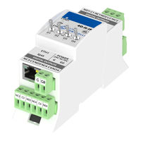
iSMA-B-MIX38-IP
iSMA iSMA-B-MIX38-IP Manuals
Manuals and User Guides for iSMA iSMA-B-MIX38-IP. We have
1
iSMA iSMA-B-MIX38-IP manual available for free PDF download: User Manual
iSMA iSMA-B-MIX38-IP User Manual (73 pages)
Modbus
Brand:
iSMA
| Category:
I/O Systems
| Size: 3 MB
Table of Contents
Table of Contents
2
1 Introduction
5
Revision History
5
Safety Rules
6
Technical Specifications
7
Summary Table for All Modules
9
Dimension
11
Power Supply Connection
12
DC Power Connection
12
AC Power Connection
12
Connecting the Communication Bus (RS485)
12
LED Indicators
13
Grounding and Shielding
14
RS485 Network Termination
14
Setting Module Address on Modbus Network
15
Baud Rate Selection
15
Protocol Selection
16
Restoring the Default Settings
16
Default Settings
17
2 Configuration Registers
18
Firmware Version and Module Type (30001)
18
Module Address (30002)
18
Baud Rate and Protocol (30003)
19
Counter of Received Messages (30004)
19
Counter of Error Messages (30006)
19
Counter of Sent Messages (30008)
19
Up Time (30012)
19
Hardware_Version (30130)
20
Mac_Address (30131)
20
Device Actions (40001)
20
Baud Rate (40136)
20
Stop Bits (40137)
20
Data Bits (40138)
21
Parity Bit (40139)
21
Response Delay Time (40140)
21
Watchdog Time (40141)
21
3 Local I/O
23
Universal Inputs Connections
23
Connection of Universal Input to Measure Voltage 0 - 10V
23
Connection of Universal Input to Measure Current 0 - 20 Ma
23
Connection of Universal Input to Measure Temperature
24
Connection of Universal Input as a Digital Input (Dry Contact)
24
Universal Inputs MODBUS Registers
25
Status of Universal Inputs Working as Digital Inputs (30017)
25
Universal Input Measure Voltage (Current) 1 - 8 (30071, 30073, 30075, 30077, 30079, 30087, 30089, 30091)
25
Universal Input Measure Temperature 1 - 8 (30072, 30074, 30076, 30078, 30080, 30095, 30097, 30099)
25
Universal Input Measure Resistance 1 - 8 (30103, 30104 - 30117, 30118)
25
Universal Input Configuration 1 - 8 (40151 - 40158)
25
Filter Time Constant of the Universal Input 1 - 8 (40159 - 40166)
26
Resolution of the Universal Inputs (40167)
26
Digital Inputs Connections
27
Connection of Digital Input (Dry Contact)
27
Digital Inputs MODBUS Registers
27
State of Digital Inputs (30016)
27
Counter 1 - 12 (40023, 40024 - 40045, 40046)
27
Resetting Counters (40022)
28
Analog Outputs Connections
28
Connection of Analog Output 0 - 10 V
28
Connecting Relay to Analog Output
28
Connection an Actuator to Analog Output
29
Analog Outputs MODBUS Registers
29
State of Analog Outputs Working as Digital Outputs (40019)
29
Value of the Analog Outputs 1 - 6 (40121 - 40126)
29
Default State of the Analog Outputs (Digital) (40144)
29
Default State of the Analog Output 1 - 6 (40145 - 40150)
30
Configuration Mode of Analog Output 1 - 6 (40168 - 40173)
30
Hand Control Status of Analog Outputs (30015)
30
Hand Control Value of Analog Outputs 1 - 4 (30125 - 20128)
31
Digital Outputs (Relays) Connections
32
Connecting the Solenoid Valve to the Digital Output
32
Connecting a Resistive Load to the Digital Output
32
Connecting a Inductive Load to the Digital Output
32
Digital Outputs (Relays) MODBUS Registers
33
State of Digital Outputs (40018)
33
Default State of Digital Outputs (40143)
33
Hand Control Status of Digital Outputs (30015)
33
Triac Outputs Connections
34
Connecting the Solenoid Valve to the Triac Output
34
Connecting a Resistive Load to the Triac Output
34
Triac Outputs MODBUS Registers
35
State of Triac Outputs (40018)
35
Default State of Triac Outputs (40143)
35
Value of the Triac PWM Outputs 1 - 4 (40121 - 40124)
35
Default State of the Triac PWM Outputs 1 - 4 (40145 - 40148)
35
Configuration Mode of Triac Output 1 - 4 (40168 - 40171)
35
Hand Control Status of Triac Outputs (30015)
36
Special Application Modes for 4I4O-H, 4I4O-H-IP, 4U4O-H and 4U4O-H-IP
37
Operation Mode Registers (40176,40180,40184,40188)
38
Time Value Registers (40177,40181,40185,40189)
41
Command Register (40020)
42
Block Inputs Register (40021)
42
Setpoint Registers (40178,40182,40186,40190)
42
Differential Registers (40179,40183,40187,40191)
42
4 WEB Configuration- Only IP Version
43
Web Server Access
43
Device Page
43
Local I/O Status and Configuration
44
Universal Inputs
44
Special Application Modes Configuration
45
Digital Inputs
46
Digital Outputs
46
Analog Outputs
47
RS485 Configuration
48
IP Configuration
49
Device Management
50
Contact
50
5 Modbus TCP/IP Modules
51
Modbus TCP/IP
51
Advertisement
Advertisement
Related Products
iSMA iSMA-B-MIX18
iSMA iSMA-B-MIX18-IP
iSMA iSMA-B-MIX38
iSMA iSMA-B-8I
iSMA iSMA-B-8U-IP
iSMA iSMA-B-8I-IP
iSMA iSMA-B-4U4A-H
iSMA iSMA-B-4TO-H
iSMA iSMA-B-4O-H
iSMA iSMA-B-4U4A-H-IP
iSMA Categories
Controller
Touchscreen
Industrial PC
I/O Systems
Control Unit
More iSMA Manuals
Login
Sign In
OR
Sign in with Facebook
Sign in with Google
Upload manual
Upload from disk
Upload from URL