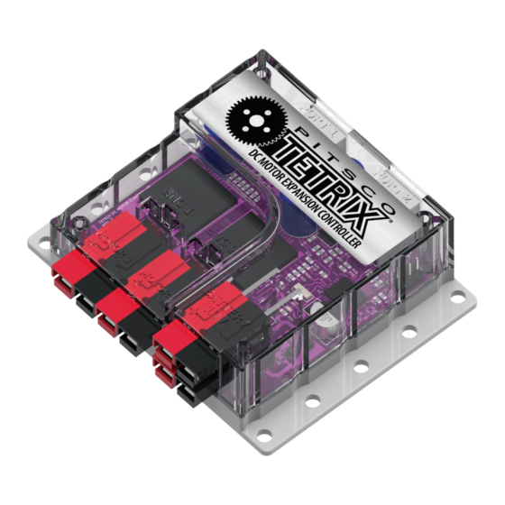
pitsco Tetrix Max User & Technical Manual
Dc motor expansion controller
Hide thumbs
Also See for Tetrix Max:
- Teachers manual (36 pages) ,
- Programming manual (28 pages) ,
- Creator's manual (23 pages)

Related Manuals for pitsco Tetrix Max


Summary of Contents for pitsco Tetrix Max
- Page 1 TETRIX® DC Motor Expansion Controller Technical Guide 44559...
- Page 2 No part of this product or related documentation may be reproduced in any form by any means without prior written authorization of Pitsco, Inc. All other product names mentioned herein might be the trademarks of their respective owners.
-
Page 3: General Description
PRIZM at one time. The onboard firmware provides a comprehensive set of programmable motor control functions. The TETRIX MAX DC Motor Expansion Controller features the following: • Connects to the PRIZM expansion port, enabling users to control up to two additional 12-volt DC motors •... -
Page 4: Important Safety Information
DC motor expansion controller. The appendix provides a detailed description of each function used by the TETRIX PRIZM Arduino Library for interfacing with the DC motor expansion controller. Please be sure Pitsco.com/TETRIX-PRIZM- to download and install the latest TETRIX PRIZM Arduino Library from the TETRIX website at Robotics-Controller#downloads. - Page 5 Attaching the DC Motor Expansion Controller The DC motor expansion controller mounting holes are spaced to align with the TETRIX hole pattern. The expansion controller can be attached to the TETRIX building elements using the screw and nut hardware included in the TETRIX robotics sets.
- Page 6 The DC motor expansion controller is designed with flexibility in mind and can interface with any master controller with an i2C communications bus. Pitsco Education provides software support materials and other resources that enable the DC motor controller to interface with the PRIZM controller, the LEGO MINDSTORMS® EV3 Brick, and the National Instruments myRIO.
- Page 7 2x Grove sensor TETRIX motor family connections controllers to NI myRIO i2C LEGO style i2C port connector for connection of TETRIX motor controllers A free downloadable TETRIX LabVIEW control palette and user documentation are available for download at Pitsco.com/Competitions,-Clubs,-and-Programs/World- Robot-Olympiad.
- Page 8 Power: 12 volts DC using TETRIX MAX NiMH fuse-protected battery pack; blue LED power indicator DC motor ports: 2 Powerpole connections; H-bridge controlled; 10 A continuous each channel; 20 A peak Recommended motor: TETRIX TorqueNADO™...
- Page 9 TETRIX MAX DC Motor Expansion Controller Library Following is a quick reference for each expansion controller function supported by the TETRIX PRIZM Arduino Library. Note: Unless changed, the default ID# for the DC motor expansion controller is 1. readDCFirmware(ID#); setExpID(ID#);...
- Page 10 TETRIX MAX DC Motor Expansion Controller Arduino Library Functions Chart Please be sure to download and install the latest version of the TETRIX PRIZM Arduino Library for the most up-to-date programming features and functionality. All the DC motor control functions that implement PID control require encoder input data. For these functions to execute accurately, the motor encoder must be a TETRIX type or one that matches the TETRIX motor encoder specification.
- Page 11 Description Function Coding Example (for controller ID = 1) Set DC Motor Power setMotorPower(ID#, motor#, power); setMotorPower(1, 1, 50); Sets the power level and direction of Data Type: Spin Motor 1 clockwise at 50% power. a TETRIX DC Motor connected to the motor ports.
- Page 12 Description Function Coding Example (for controller ID = 1) Set DC Motor Speed setMotorSpeed(ID#, motor#, speed); setMotorSpeed(1, 1, 360); Uses velocity PID control to set the Data Type: Spin Motor 1 clockwise at a constant constant speed of a TETRIX DC Motor speed of 360 DPS.
- Page 13 Description Function Coding Example (for controller ID = 1) Set DC Motor Targets setMotorTargets(ID#, speed1, setMotorTargets(1, 360, 1440, 360, target1, speed2, target2); 1440); Implements velocity and positional PID control to simultaneously set the Data Type: Spin Motor 1 and Motor 2 at a constant constant speeds and the encoder speed of 360 DPS until each motor count target holding positions of both...
- Page 14 Description Function Coding Example (for controller ID = 1) Set Motor Degrees setMotorDegrees(ID#, speed1, setMotorDegrees(1, 180, 360, 180, degrees1, speed2, degrees2); 360); Implements velocity and positional PID control to set the constant speeds and Data Type: Spin Motor 1 and Motor 2 at a constant the degree target holding positions of speed of 180 DPS until each motor both TETRIX DC Motor channels with...
- Page 15 Description Function Coding Example (for controller ID = 1) Read DC Motor Current readMotorCurrent(ID#, motor#); readMotorCurrent(1, 1); Reads the DC motor current of each Data Type: Read the motor load current of Motor 1 TETRIX DC Motor attached to the channel.
- Page 16 Description Function Coding Example (for controller ID = 1) Read Encoder Degrees readEncoderDegrees(ID#, enc#); readEncoderDegrees(1, 1); Reads the encoder degree value. The Data Type: Read the current degree count value of DC controller uses encoder pulse encoder 1 (ENC1 port). data to implement PID control of a ID# = integer TETRIX DC Motor connected to the...
- Page 17 Description Function Coding Example (for controller ID = 1) Read Battery Pack Voltage readBatteryVoltage(ID#); readBatteryVoltage(1); Reads the voltage of the TETRIX Data Type: Read the voltage of the TETRIX battery battery pack powering the controller. pack powering the controller. The value read is an integer. ID# = integer Example: A value of 918 equals 9.18 volts.
- Page 18 In-Depth Technical Specifications TETRIX MAX DC Motor Expansion Controller Command Register Map Register Name HEX Byte Write Read R/W Assembled Description Command Bytes Bytes Data Type DC_Firmware 0x26 unsigned Returns the firmware version. Set_EXP_ID 0x24 unsigned Sets/changes the i2C address/ID of the motor controller.
- Page 19 Command Register Functions Descriptions DC_Firmware: Sending the command byte 0x26 returns the motor controller firmware version. The value returned is an unsigned byte. Set_EXP_ID: Sending the command byte 0x24 followed by an ID byte causes the DC motor expansion controller to change its i2C address/ID to the value of the ID byte sent.
- Page 20 Motor1_Target: Sending the command byte 0x46 puts motor channel 1 in encoder count targeting mode. Six data bytes set the speed and encoder target value for motor channel 1. The first two data bytes represent the speed parameter in degrees per second. The last four data bytes represent the encoder 1 target count value. The motor controller firmware will assemble the first and second bytes into a 16-bit signed integer representing the Motor 1 speed parameter with the first byte being the High byte.
- Page 21 Motor1_Invert: Sending the command byte 0x51 followed by one data byte will set the invert forward/reverse mode for Motor 1. Setting the data byte to 1 will set motor channel 1 to invert mode. Setting the data byte to 0 will set motor channel 1 to non-invert mode.
- Page 22 TETRIX® DC Motor Expansion Controller Technical Guide Call Toll-Free Visit Us Online at 800•835•0686 Pitsco.com...
Need help?
Do you have a question about the Tetrix Max and is the answer not in the manual?
Questions and answers