
Subscribe to Our Youtube Channel
Related Manuals for Honeywell Thor VM1A


Summary of Contents for Honeywell Thor VM1A
-
Page 1: Quick Start Guide
Thor™ VM1A Vehicle-Mount Computer Powered by Android™ Quick Start Guide VM1A-A8-EN-QS Rev A 10/18... -
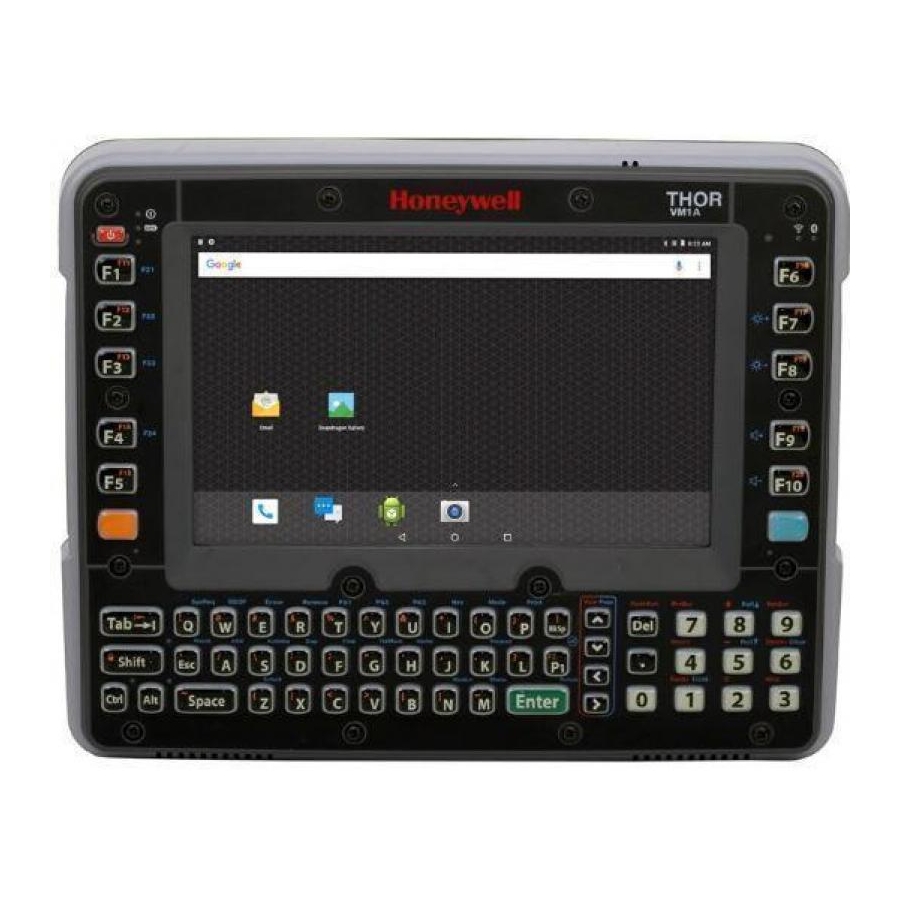
Page 2: Computer Features
Out of the Box Make sure your shipping box contains these items: • Thor VM1A vehicle-mounted computer (Model VM1A-L0N) • Regulatory Sheet If you ordered additional accessories for your computer, verify that they are also included with the order. Be sure to keep the original packaging in case you need to return the computer for service. - Page 3 Wi-Fi Wi-Fi (AUX) (MAIN) Stylus Disconnect Button Access Panel SD Card Access Panel Dock Contact Pads Provision for Provision for Quick Release Laptop Security Padlock Handle Cable...
-
Page 4: Dock Features
Dock Features Dock Contact Pads Standard Dock Strain Relief Clamps RAM Ball Fuse COM 1 COM 2 Power Connector Audio Power Switch... - Page 5 Enhanced Dock Strain Relief Clamps Accessory Accessory Mount Mount Audio Fuse COM 2 COM 1 Power Switch USB 1 USB 2 Power Connector Dock USB Client Port Ethernet...
- Page 6 Mount to Vehicle The Thor VM1A should be secured to an area in the vehicle where it: • Does not obstruct the driver's vision or safe vehicle operation. • Will be protected from rain or inclement weather. • Will be protected from extremely high concentrations of dust or wind-blown debris.
- Page 7 Attach RAM ball to the Smart Dock. Attach VM1A assembly to RAM base using RAM arm and tighten knob on RAM arm.
- Page 8 For more mounting details, refer to the user guide available at www.honeywellaidc.com. Connecting the Power Cable for 12-48 VDC Vehicles (10-60 VDC Direct Connection) Note: Refer to the Thor VM1A User Guide for other power connections, available at www.honeywellaidc.com. Caution: For installation by trained service personnel only.
-
Page 9: Power Cable Routing
Power Cable Routing... - Page 10 Wire Color Connection DC + (10-60 VDC) Red/White DC + (10-60 VDC) Black DC - Black/White DC - Green Ground Blue Ignition Sense Input (optional) Refer to the Thor VM1A User Guide, available at www.honeywellaidc.com, for further information about ignition control.
-
Page 11: Vehicle 10-60 Vdc Direct Power Connection
Vehicle 10-60 VDC Direct Power Connection The VM1A must not be mounted in the dock. The power switch on the dock must be turned Off. The power cable must be UNPLUGGED from the dock. While observing the Fuse Requirements, connect the power cable as close as possible to the actual battery terminals of the vehicle (if using unswitched power). - Page 12 • Auto On Control and Manual Control Wiring Diagram Ignition wire must be left disconnected. Existing Circuitry On Vehicle Quick Mount Smart Dock Battery Main Switch Cable for optional COM1 or COM2 screen blanking Connector connection Fuse - See Fuse Warning Red/White (if present) Black/White (if present) Circular...
- Page 13 Secure the power cable to the VM1A using the strain relief cable clamps. Place VM1A in the dock. 10. If using the Screen Blanking feature, install the screen blanking box or switch. (Refer to the Thor VM1A User Guide, available at www.honeywellaidc.com for further information about the Screen Blanking box.)
-
Page 14: Restart The Computer
Restart the Computer You may need to restart the computer to correct conditions where an application stops responding to the system or the computer seems to be locked up. Press and hold the Power button until the options menu appears. Select Reboot and then OK. -
Page 15: Limited Warranty
Trademarks Android is a trademark of Google LLC. Disclaimer Honeywell International Inc. (“HII”) reserves the right to make changes in specifications and other information contained in this document without prior notice, and the reader should in all cases consult HII to determine whether any such changes have been made. - Page 16 This document contains proprietary information that is pro- tected by copyright. All rights are reserved. No part of this docu- ment may be photocopied, reproduced, or translated into another language without the prior written consent of HII. Copyright2018 Honeywell International Inc. All rights reserved.
Need help?
Do you have a question about the Thor VM1A and is the answer not in the manual?
Questions and answers