Table of Contents
Advertisement
Quick Links
Advertisement
Table of Contents

Subscribe to Our Youtube Channel
Related Manuals for infrared industries FGA

Summary of Contents for infrared industries FGA
- Page 1 FGA4000XDS Four and Five Gas Analyzer...
- Page 3 Operator’s Manual Revision 10-17-2018 Infrared Industries 25590 Seaboard Lane Hayward, CA 94545 Phone 800.344.0321 • 510.782.8100 www.infraredindustries.com...
-
Page 5: Table Of Contents
Table of Contents ....................................6 NTRODUCTION .................................... 8 NALYZER Power UP ...................................... 8 Printer Paper Installation ................................9 ..................................10 YSTEM EATURES Front Panel ....................................10 REAR PANEL ....................................11 1 – ....................................12 HAPTER ................................ 12 ONFIGURING THE NALYZER Data Capture Option: .................................. - Page 6 Sample Hose ....................................40 Filter Assembly .................................... 40 Front Panel and Exterior ................................41 Oxygen Sensor ..................................... 41 NOx Sensor - Oxide of Nitrogen ..............................42 Routine Cleaning ..................................42 Returning the Analyzer for Service/Repairs ..........................43 6 – ....................................44 HAPTER ..................................
-
Page 7: Introduction
Introduction The analyzer allows the measurement of four or five gases in automotive exhaust. It is capable of determining volume concentrations of HC (as N-hexane), CO (carbon monoxide), CO (carbon dioxide), O (oxygen), and optionally NOx (nitric oxide). Based on gas concentrations the analyzer will calculate the Air to Fuel Ration (AFR), Lambda () and Grams per Mile (GPM) or Grams per Kilometer. -
Page 9: Analyzer Set-Up
Analyzer Set-up This section provides a description of the set-up of the analyzer. When setting up the analyzer for the first time check for any damage that may have occurred during shipment. P O W E R U P The analyzer can be operated from either AC or DC power sources. For AC connections the analyzer will accept 90 – 260 VDC. -
Page 10: Printer Paper Installation
P R I N T E R P A P E R I N S T A L L A T I O N If the analyzer was ordered with the optional embedded printer then it will be necessary at times to replenish the paper. To install paper follow the following steps: 1. -
Page 11: System Features
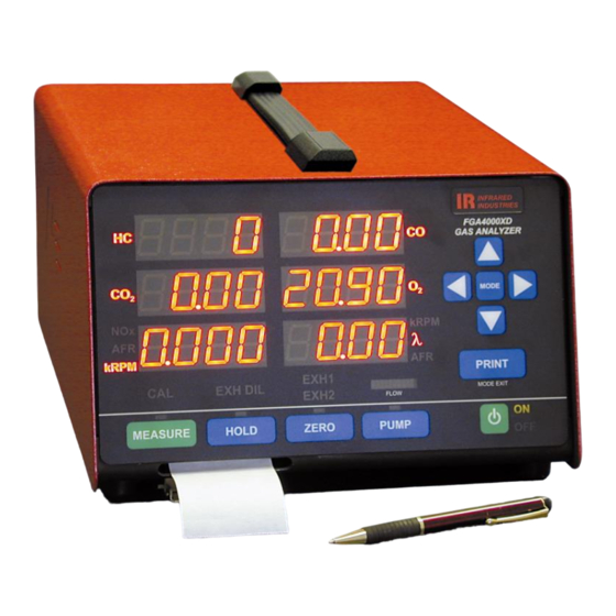
System Features F R O N T P A N E L Before attempting to operate the analyzer, review the system features described below as well as all warning labels. Identification and understanding of the physical features of the instrument will make operation easier. FGA4000XDS front panel can display six parameters: Four fixed parameters (HC, CO, CO2, and O2) and any two user-selectable parameters from NOx, AFR, RPM, and Lambda. -
Page 12: Rear Panel
The LOW FLOW Indicator bar graph will light in the red zone when the bench accuracy of any particular gas degrades by 3% or the response time exceeds the specified time (13 seconds) because of discrepancies in the sample system i.e., clogged filters, bad pump, etc. -
Page 13: Chapter 1
Chapter 1 – Configuring the Analyzer The FGA4000XDS has various configuration options that can be set by the operator. This chapter describes each of these options. To enter the configuration options press the MODE button when the analyzer is in stand-by mode. Each time the MODE button is pressed the display will advance to the next option. -
Page 14: Measure Mode Option
M E A S U R E M O D E O P T I O N : This option selects the operation mode when the MEASURE button is pressed (placed in Measure Mode). You can select to display concentrations, perform dISP unit Dual Mode measurements or perform a GPM test. -
Page 15: Leak Check
L E A K C H E C K : Leak Test This option will run a leak check of the system when YES is selected. Use ▲ or ▼ to select between yes and no. To run the test select YES and place the red cap on the end of the probe. When ready to run the test press MODE. -
Page 16: Factory Calibration Reset
At this point you must turn on your calibration gas. When the gas is on press Turn Cal MODE otherwise once again you can exit the calibration by pressing MODE EXIT. This window will now display the current concentration values for the gases. By 0000 00. -
Page 17: System Information
When you have completed the test course press the MEASURE button again to end the measurement. The display will show: At this point enter the ending odometer reading from the vehicle. When the value GPM DONE is entered press the MEASURE button again. The display will now show the computed values for GPM. -
Page 19: Chapter 2
Chapter 2 – Using the Analyzer W A R M - U P P R E - W A R M - U P L O C K O U T P H A S E The system enters the PRE-WARM-UP LOCKOUT phase when power is first applied by pressing the POWER ON/OFF switch (main front panel). -
Page 20: Measuring Gas
M E A S U R I N G G A S M E A S U R E I N I T I A T I O N Pressing the MEASURE push button will start the MEASURE sequence. The first push of the MEASURE push button lights the MEASURE indicator, takes the analyzer out of the STANDBY mode and puts it in the MEASURE mode. -
Page 21: Calibration
C A L I B R A T I O N The analyzer as shipped has been calibrated at the factory and is designed to maintain calibration accuracy for extended periods of operation. Due to the sophisticated circuitry used in the analyzer, frequent calibration is not required. However, we recommend a gas calibration about every six months to ensure the integrity of the analyzer. -
Page 22: Dual Exhaust
F I E L D C A L I B R A T I O N W I T H C E R T I F I E D C A L G A S The analyzer does not need regular field calibration. However, field calibration can be performed when there is reason to believe that the factory calibration is no longer producing accurate analysis results. -
Page 23: Tachometer
T A C H O M E T E R This menu screen allows the operator to select between a 2-cycle and 4-cycle engine. This option is required because most 4-cycle ignition engines fire only on the compression stroke or every other crankshaft revolution. 2-cycle engines fire with each revolution of the crankshaft so if your analyzer was set on 4-stroke (cycle) while measuring a 2-cycle engine;... -
Page 24: Grams Per Mile (Kilometer)
This driving test can be approximated without a dynamometer by conducting a road test instead and taking data using the Infrared Industries model FGA4000XDS engine gas analyzer. To perform this test, follow the steps below. T H E... -
Page 25: Exhaust Dilution
Start the test by pressing the MEASURE button. The display will now prompt you to enter the starting odometer reading and the engine displacement. GPM Mode odoM 000. 0 Disp 00. 0 0 Use the arrow keys (▼, ▲, ◄ and ►) to enter the values. Accelerate the VUT at a rate of approximately 3.3 mph per second for about 10 seconds or until the VUT reaches 30 mph. - Page 26 The function is enabled and the operator has an opportunity to modify the EXHAUST DILUTION threshold, by pushing the EXHAUST DILUTION push button momentarily. The threshold for the EXHAUST DILUTION function will be displayed in the top right (CO ) display [all other displays will be blank]. The operator can press the “”...
-
Page 27: Chapter 3
(CO and O2) that the Air Fuel Ratio or Lambda could be calculated from these measurements. This, in fact, is the case and the FGA 4000 series product offers an option to calculate Lambda from the gas concentrations measured. The equation used by the system to calculate Lambda is discussed in detail in Appendix C. -
Page 28: Oxides Of Nitrogen (Optional)
When a fuel mixture is "lean", there is too much air and too little fuel in the air-fuel ratio. If a mixture is "rich", it has too much fuel and too little air. Because internal combustion engines are not 100% efficient, even with ideal fuel mixtures, other substances are formed in the combustion chamber during combustion and are exhausted from the engine. -
Page 29: Hydrocarbons
H Y D R O C A R B O N S Hydrocarbons (HC) are organic compounds made up of hydrogen and carbon atoms. The HC present in gasoline engine exhaust is unburned gasoline vapor, and is measured in parts per million (PPM). HC levels in engine exhaust vary with the air-fuel ratio. -
Page 30: Carbon Dioxide
C A R B O N D I O X I D E Carbon dioxide (CO2) is a combustion byproduct formed when one carbon atom bonds with two oxygen atoms (an oxygen molecule), and by the oxidation of CO in the catalytic converter. Unlike CO, CO2 is comparatively harmless; animals give off CO2 as a byproduct of respiration. -
Page 31: Conclusion
C O N C L U S I O N Figure 10 Combustion Products Vs Lambda Figure 10 shows the relationship between the air-fuel ratio and the four exhaust gases monitored by the analyzer. It shows: HC levels are lowest when the air-fuel ratio is ideal because most of the fuel is consumed in combustion. -
Page 32: Catalytic Converters
C A T A L Y T I C C O N V E R T E R S Figure 12 Typical Catalytic Converters The first attempt at reducing emission levels in automobiles was to get the air-fuel ratios as close as possible to stoichiometric. - Page 33 As converter technology has progressed, catalysts have been developed to treat NO . In this reaction, oxygen is removed from the NO compounds, reducing them to nitrogen and oxygen. This is called a reduction reaction. Converters that combine the oxidation of HC and CO with the reduction of NO are known as three-way converters.
-
Page 35: Chapter 4
Chapter 4 – Testing U S I N G A N A L Y Z E R R E A D I N G S F O R D I A G N O S I S This exhaust analyzer is a highly versatile test instrument. In addition to testing carbon monoxide (CO), carbon dioxide (CO ), oxygen (O ), hydrocarbon (HC), and optionally oxides of nitrogen (NO... - Page 36 The chart below lists some of the kinds of problems that could result in abnormal gas readings. Possible Problem(s) Legend Rich mixture with ignition misfire = low Faulty thermostat or coolant sensor. M = moderate H = high Exhaust leak after the converter. Injector misfire, catalytic converter operating.
-
Page 37: General Tailpipe Testing Tips
G E N E R A L T A I L P I P E T E S T I N G T I P S 1. Read and follow the maintenance and calibration procedures outlined in this manual. 2. Do not test exhaust emissions on vehicles that are smoking excessively or are in obvious need of engine repair. -
Page 38: Vehicle Inspection
V E H I C L E I N S P E C T I O N E X H A U S T S Y S T E M I N T E G R I T Y 1. Air management system - Ensure that check valves are not leaking. 2. -
Page 39: Engine Conditioning
C O N N E C T I N G P R O B E H O S E T O S Y S T E M 1. Connect the FGA 4000 Analyzer power cord into a standard 120 VAC, 50/60 Hz electrical receptacle (or 240 VAC, 50/60 Hz, for analyzer set up for that voltage). -
Page 41: Chapter 5
Chapter 5 – Maintenance The analyzer requires very little maintenance. The following chart itemizes the schedule for those items that do require periodic maintenance. Component Interval Zero Vacuum Probe Each Use Sample System Hose Check As Required Filter When a LOW FLOW indication appears* Calibration Check Every Three Months Oxygen Sensor... -
Page 42: Front Panel And Exterior
S E R V I C I N G T H E F I L T E R Filter service frequency is dependent on the operating conditions. Continuous use, testing vehicles that have not been warmed-up to normal operating temperature, or testing engines that have excessive emissions will require more frequent filter service. -
Page 43: Nox Sensor - Oxide Of Nitrogen
S E R V I C I N G T H E O X Y G E N S E N S O R 1. Turn off the power to the analyzer. 2. Remove the oxygen sensor connector from the top of the sensor. 3. -
Page 44: Returning The Analyzer For Service/Repairs
E-mail: service@infraredindustries.com If it is necessary to return the analyzer, notify the seller in your area or contact Infrared Industries at the address/phone number above. You must obtain a RMA number before sending in the unit. Note the RMA number on the outside of the box. -
Page 45: Chapter 6
Chapter 6 – Troubleshooting A N A L Y Z E R T R O U B L E S H O O T I N G There are three failure modes that the analyzer might encounter: General Failure, Zero Failure, and Failure to Calibrate. For a General Failure and Zero Failure, perform the following procedure: 1. -
Page 47: Appendixa
Appendix A – Lambda Calculations B R E T T S C H N E I D E R E Q U A T I O N In order to calculate the value of Lambda from measurements of combustion by products in the exhaust of a gasoline engine, a mathematical model is necessary. -
Page 49: Appendixb
Appendix B – DAC Outputs This gas analyzer supports eight DAC output channels: Each Channel is defined as follows: Range 0 – 1, 5, 10V Description 0 – 9999 PPM 0 – 10% 0 – 20% 0 – 25% 0 – 5000 PPM NOx ( if applicable) 0 –... -
Page 51: Appendixc
The gas analyzer has an optional feature to read the tachometer value from an OBDII scanner. To use this feature you must have an adapter and scanner from Infrared Industries. The adapter plugs into the serial connector on the back of the analyzer. Each adapter is configured to be paired to a specific OBDII Bluetooth Make sure the labels on the adapter and scanner match when using this feature scanner. -
Page 53: Appendixd
Appendix D - Specifications The following specifications are subject to change without notice: P R I N C I P A L G A S E S / R A N G E S M E A S U R E D HC, CO, CO Non-Dispersive Infrared (NDIR) , and NO... -
Page 55: Appendixe
Appendix E – Warranty N O T I C E T O B U Y E R A N D / O R U S E R O F T H E A N A L Y Z E R : Exclusion of warranties and limitation of damages and remedies This analyzer is warranted against defects in materials and workmanship under normal use and service for one year from the date of delivery to the original purchaser. -
Page 57: Appendixf
Appendix F – Glossary of Terms This glossary defines terms used throughout the manual. Air-Fuel Ratio (AFR) – The ratio by volume of air to vaporized fuel in the combustion chamber of an engine. It is usually expressed as the amount of air to one part of fuel. For example the ideal mixture for most fuels is 14.7 parts of air to one part of fuel.
Need help?
Do you have a question about the FGA and is the answer not in the manual?
Questions and answers