Table of Contents
Advertisement
Quick Links
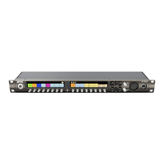
KP-5032 and KP-4016
Keypanels
Technical Manual
Lever Key and Pushbutton Versions
up to and including version 2.1.1
includes support for
Control Package and Audio Package
Rev. 05
6/2017
F.01U.304.914
Advertisement
Table of Contents


Need help?
Do you have a question about the KP-4016 and is the answer not in the manual?
Questions and answers