Table of Contents
Advertisement
Street Thunder™
Street Thunder™
Street Thunder™
Street Thunder™
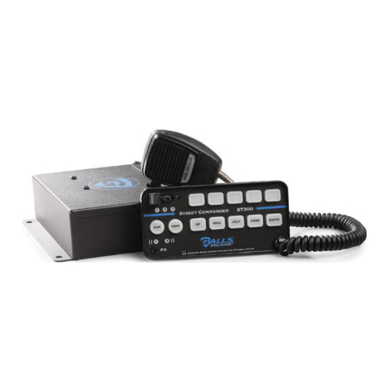
ST300
Street Commander
SIREN AMPLIFIER & LIGHT CONTROLLER
INSTALLATION AND OPERATING INSTRUCTIONS
1340 Russell Cave Road / P.O. Box 54308
Tel: (800) 477-7766
Fax: (800) 944-2557
www.galls.com
Lexington, KY 40505
PLIT301GALLS REV. D
6/18/14
Advertisement
Table of Contents

Related Manuals for Galls ST300


Summary of Contents for Galls ST300
- Page 1 Street Thunder™ Street Thunder™ Street Thunder™ Street Thunder™ ST300 Street Commander SIREN AMPLIFIER & LIGHT CONTROLLER INSTALLATION AND OPERATING INSTRUCTIONS 1340 Russell Cave Road / P.O. Box 54308 Lexington, KY 40505 Tel: (800) 477-7766 Fax: (800) 944-2557 www.galls.com PLIT301GALLS REV. D...
-
Page 2: Table Of Contents
Due to continuous product improvements, we must reserve the right to change any specifications and information contained in this manual at any time without notice. Galls and/or the manufacturer make no warranty of any kind with regard to this manual, including, but not limited to, the implied warranties of merchantability and fitness for a particular purpose. -
Page 3: Installation Information Table
_____ S3 Auto Activate General Description The ST300 series is a premium remote system that combines the siren amplifier, the siren controls, and light controls all in one system. A single slim-line remote control head combines the noise-canceling microphone with a built in siren, as well as many of the switch and light controls for the vehicle. -
Page 4: Installation
Both a PA volume and a Radio volume are provided. The ST300 series has been designed with several protection features to provide exceptional field service. Excessive high or low voltage detection will disable the siren output, protecting both the amplifier and the speaker. -
Page 5: Installer-Selectable Options (Amplifier)
Installer Selectable Options The ST300 has several options that can be selected during installation. Various DIP switches and jumpers on the printed circuit board inside the amplifier case, inside the control head. These options should be set before installation of the unit. - Page 6 (Installer Selectable Options CONT’D) Auxiliary Input Polarity Diagram showing NEG AUX set up Applying a positive voltage to the green wire normally activates the auxiliary function (Air Horn standard/MANUAL function optional). To have the AUX function instead activate when the green wire is connected to ground (negative) . 1.
- Page 7 (Installer Selectable Options CONT’D) Two-Tone If desired, the Phaser sound can be replaced with a Two-Tone sound. This can be done by turning on (up position) DIP switch #3 in the amplifier (labeled SW). (See Amplifier diagram above) Phaser Disable If desired, the Phaser function can be completely disabled by turning on (up position) DIP switch #4 in the amplifier (labeled PD).
- Page 8 (Installer Selectable Options CONT’D) Pursuit Disable (Siren) The farthest right slide switch position (L3) will normally activate the siren output in the wail mode, along with all three light functions. Automatic activation of the siren and arrow stick can be disabled. If you prefer to NOT have the siren and arrow stick automatically activated when the slide switch is moved to position three, move Dip switch #2 in the amplifier (labeled PS) to the “UP”...
-
Page 9: Installer-Selectable Options (Control Head)
(Installer Selectable Options CONT’D) CONTROL HEAD OPTION JUMPERS The control heads are shipped with the standard features listed below. The seven jumpers are all installed across both pins when the siren is shipped. By moving the jumpers onto only one pin the alternate operation may be selected. (S3 Auto Activation is achieved by removing the "Momentary"... - Page 10 (Installer Selectable Options CONT’D) These two jumpers are shown moved from their default position to only one pin. - Auxillary control S3 Auto Activate - - 8 Second (S4) place one jumper - Momentary (S3) over both these pins - Normally closed contact (S3) - Hands Free on start up - Horn Ring Transfer on start up - Audible beep disable...
-
Page 11: Mounting
Mounting SAFETY PRECAUTIONS For the safety of the installer, vehicle operator, passengers and the community please observe the following safety precautions. Failure to follow all safety precautions and instructions may result in property damage, injury or death. WARNING DO NOT mount in air bag deployment area. Devices should be mounted only in locations listed in SAE standard J1849. - Page 12 (Mounting CONT’D) STANDARD CONTROL HEAD The standard control head comes with two interchangeable “U” brackets. 1. Using one of the two “U” brackets as a template, mark at least two mounting holes on your mounting surface. 2. Drill the mounting holes in the vehicle taking care to check the backside of the surface you are drilling into.
- Page 13 (Mounting CONT’D) MICROPHONE BRACKET A metal clip is provided for mounting the microphone. Choose a location convenient to the operator and away from any air bag deployment areas. Using the mounting clip as a template, mark the two holes to be drilled. Using a 1/8" drill bit, drill the two mounting holes.
-
Page 14: Electrical Connections (Siren Amplifier)
Electrical Connections Wire Size and Termination The wiring diagrams on pages 14 and 17 show the minimum wire size used for each connection, along with recommended lead color. If the wire is longer than 10 ft., use the next larger wire size. Use only high quality crimp connectors. - Page 15 (Electrical Connections CONT’D) The power supply of the siren unit must be capable of delivering peak currents up to 50 amps for adequate short circuit protection and reliable operation. The preferred source is directly at the vehicle battery. The unit is internally fused. The wiring diagram on the next page shows detail of how to wire the power connector on the amplifier to the vehicle.
-
Page 16: Siren Wiring Diagram
(Electrical Connections CONT’D) -14-... -
Page 17: Optional Hrt Wiring Diagram
(Electrical Connections CONT’D) Horn Ring Transfer (HRT) Wiring Diagram Use this wiring diagram if you are connecting the Orange wire to utilize the Horn Ring Transfer Feature. This feature de-activates the vehicle horn while pushbutton switch S5 is activated. The diagram below shows wiring for both positive and ground-side switched horns, using an installer-supplied relay. -
Page 18: Electrical Connections (Lights)
(Electrical Connections CONT’D) LIGHT RELAY CONTROL BOX CONNECTIONS (Amplifier box) L1 & L2 L1, L2, & L3 Control Head OFF L1 L2 L3 HORN WAIL YELP PHSR RADIO (REFER TO LIGHT WIRE DIAGRAM ON NEXT PAGE, AS WELL AS TO WIRE SIZE TABLE ON PAGE 12 FOR PROPER WIRE SIZES!) The electrical connections for input power, slide switch outputs, and the push button outputs are made to the control box (amplifier) using terminal blocks (top diagram above). -
Page 19: Light Wiring Diagram
(Electrical Connections CONT’D) -17-... -
Page 20: Button Label Insertion
Testing - Test all siren functions after installation to assure proper operation. Test vehicle operation to assure no damage to vehicle. Label Insertion Once the wire connections have been made to S1 through S5, labels can be inserted into the switches. The product is shipped with 30 different labels for these push buttons. -
Page 21: Operation
Operation GENERAL This unit is designed for easy operation under the stress associated with high-speed pursuit. Most light and siren functions are accessible with one simple motion of the slide switch. LIGHT SLIDE SWITCH The slide switch is designed for quick pursuit mode operation. The far left position (OFF) will not activate any outputs. -
Page 22: Siren Controls
(Operation CONT’D) The seven push buttons across the middle of the control head allow full siren operation. When not activated, these buttons are backlit in green for nighttime viewing. When activated, an audible beep is heard, and the backlighting turns red. MAN (Manual ) In stand-by (no tone) or in the Hands Free Mode, this momentary push button switch provides a manually activated Wail siren tone while being... - Page 23 (Operation CONT’D) Siren Mode Speaker By Default, Activating the Green Auxiliary Selected: Output: Wire Changes the Speaker Output to: WAIL Wail Air Horn YELP Yelp Air Horn PHSR Phaser Air Horn Steps through from Standby to Wail to Yelp No Output (Hands to Phaser then repeats.
-
Page 24: Volume Controls
(Operation CONT’D) VOLUME CONTROLS Radio Repeat Volume The radio repeat volume is located within the rear access cover of the amplifier. This should be set when the vehicle is parked. First set the volume level of the vehicle’s two-way radio to its normal operating volume. Press the RADIO button of siren controls. -
Page 25: Service
Troubleshooting Symptom Possible Cause Check No power No power supplied to +12 terminal Does back-lighting come on? block inputs in amplifier Connector loose Do you hear a “pop” when turned on? Amplifier 20A fuse or 5A fuse Is power hooked up backwards? Positive blown ground vehicle? Is an external fuse or circuit breaker used? -
Page 26: Fuses
S1, S2, S3, S4 (Push buttons) 4-position Eurostyle terminal block S5 (Push button) flying lead Amplifier: 2-1/2” High, 7” Wide, 7-3/8” Deep (plus 3/4" flange on each side) Size Control Head Face Plate: 3-5/16" High X 6-13/16" Wide X 11/16" Deep Boxed Weight ST300: 8.5 lbs. -24-... -
Page 27: Parts
Please contact Galls Customer Service Department at (800) 477-7766. After 60 Days: Please contact the manufacturer at (585) 226-9025. If you have any questions concerning this or any other Galls product, please contact our Customer Service Department at (800) 477-7766. -25-... -
Page 28: Limited Warranty
During this warranty period the obligation of Galls is limited to repairing or replacing, as Galls may elect, any part or parts of such product which after examination by Galls is determined to be defective in material and/or workmanship.
Need help?
Do you have a question about the ST300 and is the answer not in the manual?
Questions and answers