Table of Contents
Advertisement
Installation and Operating Instructions
Installation and Operating Instructions
Installation and Operating Instructions
Installation and Operating Instructions
Due to continuous product improvements, we must reserve the right to change any
specifications and information contained in this manual at any time without notice.
and/or the manufacturer make no warranty of any kind with regard to this manual, including,
but not limited to, the implied warranties of merchantability and fitness for a particular purpose.
Galls and/or the manufacturer shall not be liable for errors contained herein or for incidental or
consequential damages in connection with the furnishing, performance, or use of this manual.
1340 Russell Cave Road / P.O. Box 54308 Lexington, KY 40505
Tel: (800) 477-7766
Street Thunder
Street Thunder
Street Thunder
Street Thunder
ST240
ST240
ST240
ST240
SIREN
SIREN
SIREN
SIREN
NOTICE
Fax: (800) 944-2557
www.galls.com
™ ™ ™ ™
Galls
PLITSTR312 REV. D
10/28/13
Advertisement
Table of Contents

Related Manuals for Galls Street Thunder ST240


Summary of Contents for Galls Street Thunder ST240
- Page 1 Galls and/or the manufacturer shall not be liable for errors contained herein or for incidental or consequential damages in connection with the furnishing, performance, or use of this manual.
-
Page 2: Table Of Contents
Installation Information MODEL: ST240 Serial #: PURCHASE DATE: INSTALLATION DATE: INSTALLER: DEALER: Model and serial number located on bottom of unit TABLE OF CONTENTS GENERAL DESCRIPTION INSTALLATION NOTES MOUNTING TIPS ELECTRICAL CONNECTIONS Wiring Guide Wiring Diagram Mandatory Connections Optional Connections INSTALLER SELECTABLE OPTIONS DIP Switch Settings (AUX &... -
Page 3: General Description
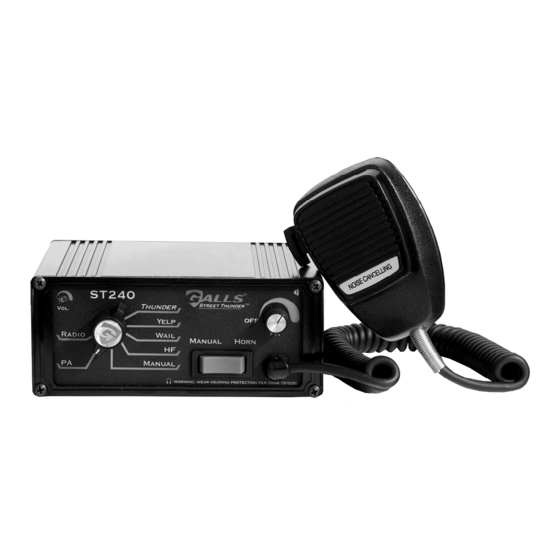
General Description The ST240 Siren Amplifier is a premium 200W unit designed for dual 100W speaker use. The primary operating modes are Thunder, Yelp, Wail, Hands Free, Manual, PA, and Radio. A Noise Canceling PA Override and push-button Horn Override are available in all modes. -
Page 4: Electrical Connections
Electrical Connections Wire Size and Termination Electrical connections to this unit are made through the green 12-terminal connector located in the rear of the unit (See below - Part # CPSS-153). Examine the charts below to determine the proper gauge of the wire to use. Please review the following recommendations when making your electrical connections: •... -
Page 5: Wiring Diagram
(Electrical Connections CONT’D) CPSS-153 For ease of installation, you can remove (Please note that this is an upside-down view) the green connector from the siren while connecting your wires. Please note that when referencing terminal numbers using the wiring diagram on the previous page, the siren should be held upside down so the screw heads face UP, as pictured to the right. -
Page 6: Installer Selectable Options
Installer Selectable Options The ST240 has several options that can be selected prior to installation by using either the two DIP switches located on the back of the unit, or by using the “tone programming” button on the back in combination with the knob and/or buttons on the front of the unit. -
Page 7: Installer Selectable Options
(Installer Selectable Options CONT’D) Optional Tones Tones For WAIL, YELP, and Tones for HORN Button Tones For MANUAL Button & AUX Wire THUNDER, and Thunder Step-Up Function 1 STANDARD AIR HORN (AUX default) 1 STANDARD AIR HORN (default) 1 WAIL (Wail default) §, *, † 2 LOW FREQUENCY AIR HORN 2 LOW FREQUENCY AIR HORN 2 YELP (Yelp default) §, *... -
Page 8: Operation
Operation General This unit is designed for easy operation under the stress associated with high-speed pursuit. Most siren functions are accessible with one simple motion without repetitive activation of switches or automatic timed switching that can interfere with desired operation. Power/PA Knob The Power/PA knob is located in the upper right hand corner of the front face. -
Page 9: Manual/Horn Button
(Operation CONT’D) The front panel of the ST240 contains a two-way momentary switch for the Manual function and the Air Horn. MANUAL Rotary Switch Position Function When MANUAL Pressed MANUAL or HF Produces a rising siren tone while being pressed. The siren output “winds down”... -
Page 10: Troubleshooting
Troubleshooting Speaker Diagnostics There is a diagnostic LED shaped like a speaker located in the upper right hand corner of the front panel. This LED will only turn on while a tone is trying to be generated. It can be used to help identify the siren/speaker status. Steady - Speaker is connected and operating properly. -
Page 11: Specifications
Specifications Input Voltage 10 - 16 VDC (negative ground) Input Current 8.0 Amps @ 13.6 VDC (single 100W speaker) 16 Amps @ 13.6 VDC (dual 100W speakers) Standby Current Switch Off/Backlighting Off - Less than 4 mA Switch On/Backlighting Off - Less than 7 mA Switch Off/Backlighting On - Less than 40 mA ≈... -
Page 12: Warranty
During this warranty period the obligation of Galls is limited to repairing or replacing, as Galls may elect, any part or parts of such product which after examination by Galls is determined to be defective in material and/or workmanship.
Need help?
Do you have a question about the Street Thunder ST240 and is the answer not in the manual?
Questions and answers