
Related Manuals for Fremco MiniFlow RAPID


Summary of Contents for Fremco MiniFlow RAPID
- Page 1 OPERATING MANUAL MiniFlow RAPID 101-10031 Operating Manual 2016-06-15 EN From Serial No. 9328.1193 Fremco A/S Ellehammervej 14 9900 Frederikshavn Denmark Tel. +45 72 30 12 13...
-
Page 2: Table Of Contents
Table of Content Technical Specifications ............................3 MiniFlow RAPID ............................3 Hydraulic Control Unit ..........................4 Identification ................................5 Application ................................5 Mounting ................................5 Supply of Compressed Air and Hydraulic Pressure ..................5 Fiber Cable Blowing .............................. 5 Maintenance ................................6 Safety Directions .............................. -
Page 3: Technical Specifications
Technical Specifications These specifications cover MiniFlow RAPID and the hydraulic control unit. MiniFlow RAPID Manufacturer Fremco A/S Ellehammervej 14 9900 Frederikshavn Denmark Item No..............................101-10031 Micro cable diameter ..........................4-12 mm Micro duct diameter ..........................7-20 mm Blowing distance¹ ..........................Up to 3.5 km Blowing speed¹... -
Page 4: Hydraulic Control Unit
Hydraulic Control Unit Manufacturer Fremco A/S Ellehammervej 14 9900 Frederikshavn Denmark Item No............................... 103-10041 Hydraulic connection ......................0>125 bar, 17 l/min Manometer ..............................160 bar Hose to fiber blowing machine ......................1500 mm Hose to hydraulic pump ........................1500 mm Length ................................ -
Page 5: Identification
MiniFlow RAPID. The machine type can be identified by the type plate on the machine. NOTE: Do not use compressed air The type plate provides information about... -
Page 6: Maintenance
Use the Pushing Power Indicator (PPI) on the MiniFlow RAPID to monitor the pushing force on the fiber cable. CABLE DAMAGE SAFETY Pushing force in Miniflow RAPID has a unique kilogram monitoring system, which continuously monitors the pushing force applied on the fiber cable,... -
Page 7: Safety Directions
Safety Directions Use hearing protection, if the hydraulic Make sure to disconnect the machine from pump or other noisy equipment is placed all power sources, like air compressor and nearby. hydraulic pump, before any kind of adjustment and maintenance takes place. ... -
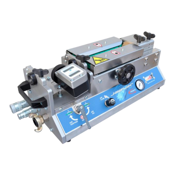
Page 8: Machine Overview
Machine Overview Adaptor plates Inlet guide (2 sets) Digital counter (speed and distance) Pushing Power Connections for Indicator (PPI) hydraulics and Hand wheel for compressed air chain adjustment Air flow regulator Air pressure manometer Air valve 101-10031 OPERATING MANUAL ©2016-06-15 EN The material is copyright protected... -
Page 9: Photo Guide, Operation
Photo Guide, Operation Before Operation Does the diameter of the nylon inlet guide bush fit the actual fiber cable, ensuring fiber cable entry in the middle of the chain groove? Size can be wrong Extensive wear can make the hole oval Is chain tension correct? Chains should be tightened to an extent that they can be lifted only 3-5 mm from the chain support rail. -
Page 10: Preparing Operation
Preparing Operation It is recommended to reduce friction between Open the air valve. Adjust the air flow duct and fiber cable by using a suitable regulator to a sufficient level to let the lubricant, which can be distributed to the inner compressed air push the foam plug through surface of the duct using the following the duct... -
Page 11: During Operation
During Operation Lubricate the chains regularly. Use a chain oil The chain pressure on the fiber cable should be sufficient to create enough friction. spray of good quality. Spray the chains with oil through the holes in the chain covers. Be ... -
Page 12: Photo Guide, Chain Maintenance And Adjustment
Photo Guide, Chain Maintenance and Adjustment Keep the chains well adjusted and clean from dust and dirt. Lubricate regularly with a water- proof chain oil spray. Please follow below instructions on both chains. Tighten the chains Remove the chain covers ... -
Page 13: Photo Guide, Pushing Power Indicator (Ppi) Adjustment
Photo Guide, Adjustment of Pushing Power Indicator (PPI) The offset point of the PPI indicator can be adjusted. This can be necessary when the machine has been in operation for some time. Use a 5 mm hex key to adjust the Allen screw placed behind the hole above the lifting handle ... -
Page 14: Photo Guide, Changing Adaptor Plates
Photo Guide, Changing Adaptor Plates The brass adaptor plates can be changed without the use of tools The adaptor plates are locked at the top and bottom by a spring loaded ball lock Ball lock Ball lock bottom ... -
Page 15: Photo Guide, Changing Chains And/Or Chain Support Rails
Photo Guide, Changing Chains and/or Chain Support Rails Remove the chain covers Remove the upper part by unscrewing the two Allen screws Remove the chain support rail Check for wear and replace, if necessary Unscrew the Allen screw in the middle of the chain wheel ... -
Page 16: Photo Guide, Initial Adjustment Of Joystick
Photo Guide, Initial Adjustment of Joystick Preparation Connect the hydraulic MultiPower Pack to the control valve Connect the control valve to the machine Start the hydraulic power unit according to operating instructions Check that there is no fiber cable in the blowing machine ... -
Page 17: Adjustment
Adjustment Turn the SPEED valve handle clockwise to full stop (= zero speed) Turn the POWER valve handle clockwise to full stop (= full power) Activate the joystick to forward operation Turn the SPEED valve handle counterclockwise until the machine starts to run smoothly (approx. - Page 18 Adjustment Turn the POWER valve handle counterclockwise until the machine stops Turn the POWER valve handle clockwise until the machine starts to run smoothly (between 40 and 50 bar on the manometer) Release the joystick to neutral Turn off the hydraulic MultiPower Pack 101-10031 OPERATING MANUAL ©2016-06-15 EN The material is copyright protected...
-
Page 19: Photo Guide, Operating The Joystick
Photo Guide, Operating the Joystick Preparation Make sure that the fiber cable and the duct are in place in the blowing machine Start the hydraulic MultiPower Pack according to operating instructions Make sure air supply is connected 101-10031 OPERATING MANUAL ©2016-06-15 EN The material is copyright protected... -
Page 20: Start-Up
Start-Up Activate the joystick to forward operation Turn the POWER valve handle clockwise to add power, if necessary Adjust to appropriate speed by turning the SPEED valve handle (look at speed m/min read-out) Open the compressed air valve on the machine after appropriate time 101-10031 OPERATING MANUAL ©2016-06-15 EN The material is copyright protected... -
Page 21: Important Note Regarding Power And Speed Adjustment
IMPORTANT Note regarding POWER and SPEED Adjustment Please be aware that POWER (oil pressure) and SPEED (oil flow) can vary during operation due to various factors like: Oil type/viscosity Oil temperature Variations in hydraulic power source Etc. 101-10031 OPERATING MANUAL ©2016-06-15 EN The material is copyright protected... -
Page 22: Ec Declaration Of Conformity
EC Directives 2006/42/EC Fremco A/S Ellehammervej 14 DK-9900 Frederikshavn Denmark Niels Søgaard Hansen General Manager 01.04.2012 Fremco A/S ● Ellehammervej 14 ● 9900 Frederikshavn ● Denmark ●Tel. +45 72 30 12 13 101-10031 OPERATING MANUAL ©2016-06-15 EN The material is copyright protected...
Need help?
Do you have a question about the MiniFlow RAPID and is the answer not in the manual?
Questions and answers