Table of Contents
Advertisement
Quick Links
Advertisement
Table of Contents

Related Manuals for Fremco MicroFlow TOUCH


Summary of Contents for Fremco MicroFlow TOUCH
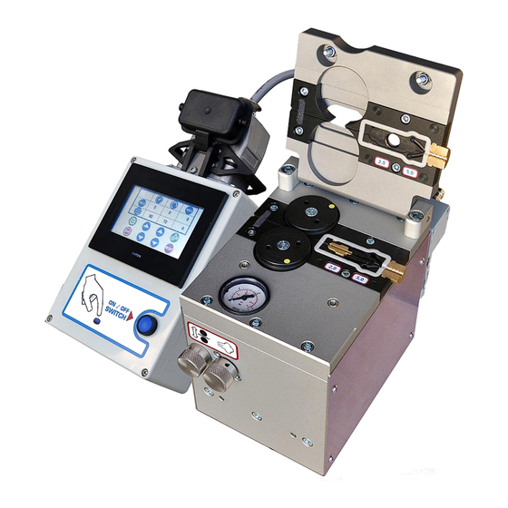
- Page 1 OPERATING MANUAL MicroFlow TOUCH 101-10051 Operating Manual 2017-01-31 EN From Serial No. 9328.1382 Fremco A/S Fremco A/S Ellehammervej 14 Ellehammervej 14 9900 Frederikshavn 9900 Frederikshavn Denmark Denmark Tel. +45 72 30 12 13 Tel. +45 72 30 12 13...
-
Page 2: Table Of Contents
Table of Contents Technical Specifications ............................3 Safety Instructions ..............................4 Maintenance ................................4 Identification ................................5 Application ................................5 Mounting and Preparations ..........................5 Supply of Compressed Air and Electricity ......................5 Fiber Protection Technology ..........................6 Fault Sequence ............................6 Display Symbols .............................. -
Page 3: Technical Specifications
Technical Specifications These specifications cover MicroFlow TOUCH as well as the control unit and the adaptor plates belonging to it. The adaptor plates are replaceable and must fit the actual size of fiber cable and microduct to be used. Manufacturer... -
Page 4: Safety Instructions
Safety Instructions Read and understand this operating The operator must make sure that no manual before operating the MicroFlow. other persons are close to the machine and Follow all safety instructions. Failure to cable drums in a way that could be follow the instructions may lead to dangerous when the machine is started. -
Page 5: Identification
MicroFlow TOUCH uses 24V DC and can be case. connected to 100-240V AC, 50/60 Hz with the included transformer. The 100-240V AC power supply must be stable and at least 2A. -
Page 6: Fiber Protection Technology
Fiber Protection Technology MicroFlow TOUCH has a unique protection The machine will also stop automatically if the technology securing that there is no damage to motor exceeds the preset maximum torque the fiber cable. The protection technology level (see section about Torque Off-Set for the... -
Page 7: Display Symbols
Display Symbols Start Book-service Indicates machine is Info: it is time to book an running authorized service check Forward Motor direction, press to Press to go to setup page toggle between forward and reverse Reverse Setup Motor direction, press to Press to set stop length. -
Page 8: Running The Fiber Blowing Machine
Running the Fiber Blowing Machine Prepare the fiber cable and place it inside After 10-20 meters, turn on air. Gradually the fiber blowing machine. Adjust the drive increase air supply as the blowing is wheels until they are tight around the fiber proceeding. -
Page 9: Use Of Control Unit
Use of Control Unit The control unit is used for operating the fiber blowing machine as well as adjusting the different parameters, for instance speed and torque level. TOUCH Display used to monitor and adjust various parameters ON/OFF Switch starts and stops the machine Adjustable Parameters ADJUST To avoid overload of the fiber cable, it is possible to adjust the maximum torque... -
Page 10: Touch Display Screen Overview
TOUCH Display Screen Overview Startup/Pause Window Shown during startup, or when machine has been inactive for some time. Tab to activate main screen. Main Window This window is shown during machine operation. On this screen it is possible to: Set and reset stop length, by pressing set length, and to reset (set to 0 disables... - Page 11 Motor Ramp Setup In this window the acceleration/deceleration ramps during motor start/stop, can be increased/decreased by pressing Press to go back to setup window Press to go back to main window Keypad For entering length stop Fiber Protection Warning Popup window when fiber protection monitor is activated.
- Page 12 Fiber Protection and Motor Torque Warning Popup window when a combination of fiber protection and motor torque occur during automatic restart cycle. Press to confirm and go to main window Service Reminder Info window shows during startup when it is time for a service check of the machine.
-
Page 13: Torque Off-Set
Torque Off-Set Adaptor Plates It is important that the adaptor plates fit the actual size of the fiber cable and the microduct. Below is an overview of the different adaptor plate components for MicroFlow TOUCH. Drive Wheels Gaskets for adaptor plates... -
Page 14: Ec Declaration Of Conformity
Director Research & Development Ellehammervej 14, DK-9900 Frederikshavn Attested by: Kim Lindblad Carlsen Managing Director Frederikshavn, 25.01.2017 Fremco A/S ● Ellehammervej 14 ● 9900 Frederikshavn ● Denmark ●Tel. +45 72 30 12 13 101-10051 OPERATING MANUAL ©2017-01-31 EN The material is copyright protected...
Need help?
Do you have a question about the MicroFlow TOUCH and is the answer not in the manual?
Questions and answers