
Related Manuals for Axminster AWEPT106


Summary of Contents for Axminster AWEPT106
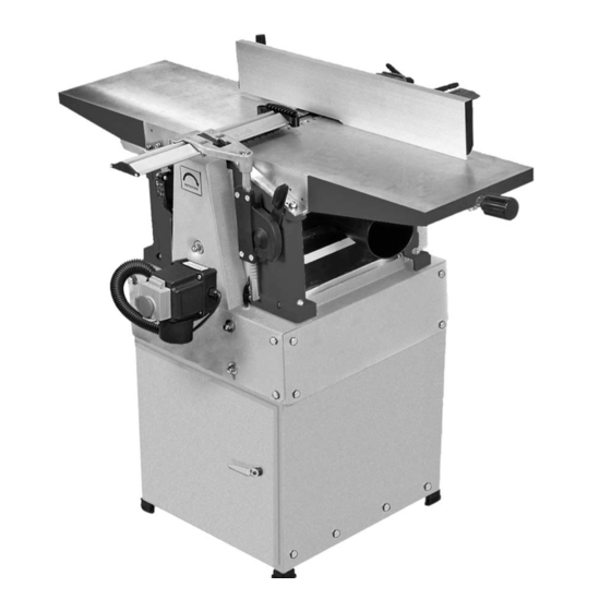
- Page 1 Code 501250 AWEPT106 260mm Planer Thicknesser Axminster Tool Centre, Unit 10 Weycroft Avenue, Axminster, Devon EX13 5PH axminster.co.uk...
-
Page 2: Declaration Of Conformity
Index of Contents Page No Index of Contents Declaration of Conformity What’s in the Box General Instructions for 230V Machines 04-05 Specification Assembly 07-08-09 Illustration and Parts Description 10-11-12-13-14-15-23-24-25 Parts Breakdown 16-17-18-19-20 Parts List 21-22 Setting Up the Machine Operating Instructions (Overhand Planing) 27-28 Operating Instructions (Thicknessing Changing the Planer Blades... - Page 3 What’s in the Box Quantity Item Model Number 1 No. Planer Thicknesser Model No. PT260 1 No. Outfeed Table 1 No. Infeed Table 1 No. Infeed Table Adjusting Screw 1 No. Guide Fence and Bracket 1 No. Packet containing Power Lead 1 No.
-
Page 4: General Instructions For 230V Machines
General instructions for 230V Machines Good Working Practices/ Safety The following suggestions will enable you to observe good working practices, keep yourself and fellow workers safe and maintain your tools and equipment in good working order. KEEP TOOLS AND EQUIPMENT OUT WARNING!! OF THE REACH OF YOUNG CHILDREN Mains Powered Tools... - Page 5 General instructions for 230V Machines If you wear your hair in a long style, wearing a cap, safety helmet, hairnet, even a sweatband, will minimise the possibility of your hair being caught up in the rotating parts of the machine, likewise,consideration should be given to the removal of rings and wristwatches, if these are liable to be a ‘snag’...
- Page 6 Specification Model AWEPT106 Rating Hobby Power 2.2kW Feed Speed 3.5m/min Cutterblock Speed 6,500 rpm Max Thicknesser Capacity 160mm Max Planing Width 260mm Max Depth of Cut Max Depth of Cut Thicknesser Max Depth of Cut Planer Knives HSS(Disposable) x 2...
- Page 7 Assembly Having unpacked your planer/thicknesser (see Step 2 below) and its accessories, please dispose of any unwanted packaging properly. The cardboard packaging is biodegradable. Please unpack your new machine and check that all the components against the “What’s in the Box” list. Care should be taken when removing the main assembly of the planer thicknesser from the box, (a) it is heavy and (b) the motor control and junction...
- Page 8 Assembly Identify the infeed table. It has the guide fence Step 5 mounting bolted on one side (see fig 5) and on the opposite side there is an engraved line which will be the infeed setting reference mark (see fig 9). Identify the infeed table adjusting screw.
- Page 9 Assembly Fitting the Infeed Table The table should now be able to move, if it doesn’t, slacken a shade more. (Please note that the adjusting movement is quite stiff, as the table lugs are captured with only a small clearance to allow movement, but maintain rigidity when the machine is used in the overhand mode.
- Page 10 Illustration and Parts Description Infeed table Capping strip Cross bar adjusting screw Fig 1 Fig 2 Shaped cut out in dust extraction hood Upper guard assembly raise Fig 3 and lower lever Motor mounting plate securing nuts...
- Page 11 Illustration and Parts Description Fig 4 Infeed table adjusting Infeed table handle adjusting screw Guide fence Rise & fall handle for mounting bracket thicknesser bed Fig 5 Anti-kick Outfeed table back fingers clamps Upper guard slide lock Peg dowel Anti-kickback fingers Peg dowel Outfeed table clamps...
- Page 12 Illustration and Parts Description Infeed table adjusting handle Fig 6 Dust extractor Chip deflector Upper guard assembly Typ. threaded corner spindle Thicknessing depth scale and pointer Adjusting grub screw Fig 7 Actuating bracket Microswitch Sprung stop Sprung bobbin...
- Page 13 Illustration and Parts Description Upper guard assembly Thicknessing bed rise and fall handle Upper guard rise and lower lever Guide fence Outfeed table Infeed table adjusting knob handle Infeed table Dust extractor Chip deflector (closed position) Thicknessing bed Main chassis NVR On/Off assemby switch assembly...
- Page 14 Illustration and Parts Description Stand assembly A preformed metal stand that encloses the motor. The main chassis (See Fig 8) assembly is bolted to it. The whole is then bolted to the cabinet stand. Main chassis The main body of the machine that all the other parts are mounted upon. assembly (See Fig 9) Infeed table...
- Page 15 Illustration and Parts Description Thicknessing bed rise and fall handle Upper cutter block guard Outfeed table assembly Infeed scale Guide fence and index mark Capping Strip Infeed table Outfeed table clamp Stand assembly Fig 9 Main chassis assembly...
- Page 16 Parts Breakdown Fig 10...
- Page 17 Parts Breakdown...
- Page 18 Parts Breakdown Fig 11...
- Page 19 Breakdown...
- Page 20 Breakdown Fig 12 Cabinet...
- Page 21 Parts List (Part 1)
- Page 22 Parts List (Part 2)
- Page 23 Illustration and Parts Description Thicknesser feed A moulded cover mounted on the off side of the main chassis, secured drive cover by two domehead nuts. (See Fig 13) Dust extraction A moulded plastic hood with a 100mm dust extraction port. When hood fitted in the void over the thicknessing table during the planing (See Fig 13)
- Page 24 Illustration and Parts Description Typ. outfeed Thicknesser bed rise table clamp & fall crank Chip deflection hood Guide fence assembly Infeed table adjusting knob Dust extraction hood Dead space plate Thicknesser feed drive cover Fig 13...
- Page 25 Illustration and Parts Description Tilt scale & pointer Tilting action clamp Fig 14 Infeed table adjusting handle Clamping bolt Tilting action clamp Fig 15 Preset 45˚ stop Typ. fore & aft adjustment of guide clamp bolt 90˚ Preset...
-
Page 26: Setting Up The Machine
Setting Up the Machine NOTE. The top edge of the planer blade should be in line with the top of the outfeed table, and the infeed table when the infeed table is registered at zero cut. The machine is ‘factory’ set, but if you have any doubts, or if, in the course of usage the machine sustains a ‘knock’... - Page 27 Operating Instructions (Overhand Planing) Note. There is an electronic braking system on your machine, which works by switching the ‘run’ capacitor. When you stop the machine after it has been running, you will hear a “click, click” sound as the brake activates, and the motor will slow down quite quickly. Please be aware that the effectiveness of the braking action is dependent on the ‘run’...
- Page 28 Operating Instructions (Overhand Planing) 11. Select an ‘edge’. (The second planing operation). Ensure that, if possible, you are not planing against the grain, and that if the stuff is bent, that the back of the bow is uppermost. 12. If necessary, alter the infeed table setting as required for planing the edge. 13.
- Page 29 Operating Instructions (Thicknessing) Additional Note. To carry out the thicknessing operation; the interlocks are set such that you require the dust extraction hood removed from the thicknessing table void and the outfeed table removed, (which allows the chip deflecting hood to be swung up and over the table to act as the cutter block guard as well as the chip deflector).
- Page 30 Changing the Planer Blades DISCONNECT THE PLANER FROM THE MAINS SUPPLY Planer blade fixing system The cutter block has two plane iron slots machined into it to take the planer blades and their securing components. The trailing edge of each slot is set at the precise angle required by the blade to plane the material efficiently.
- Page 31 Changing the Planer Blades Changing the Blades Clean the chip breaker of any accumulated resin (Tip: Screw the middle grubscrew out of the way etc., and clean the plane iron slot thoroughly. If the and adjust using the two end ones. blade has only been used on the one edge, clean, remove any accumulated resin etc, and refit to the When the blade is set and pinched in;...
- Page 32 Running In and Periodic Maintenance After the initial 5-10 hours of operation, remove At least once a week, clean either with brush the Drive belt cover and check the belt or compressed air, all the debris, dust, etc., tension. etc., on the 4 threaded corner spindles (see fig A steady push of some 5lb force should C) of the thicknessing bed rise and fall produce a deflection of between...
- Page 33 Running In and Periodic Maintenance Fig B chain drive Threaded corner spindle Fig C...
- Page 34 Notes...
- Page 35 Notes...
- Page 36 Please dispose of packaging for the product in a responsible manner. It is suitable for recycling. Help to protect the environment, take the packaging to the local recycling centre and place into the appropriate recycling bin. Only for EU countries Do not dispose of electric tools together with household waste material.
Need help?
Do you have a question about the AWEPT106 and is the answer not in the manual?
Questions and answers