Advertisement
Quick Links
Buzzer Unit BU01 Installation Guide
Check the supplied accessories
Check the following table to see which parts are needed for each model, then follow the procedures to install the buzzer.
The following lists all included parts except for this manual. If parts are missing or damaged, please contact the retailer.
Supplied accessories
Bracket
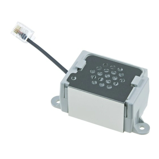
Buzzer
mC-Print3 Series
Not Used
Used
SP700 Series
Not Used
Used
TSP100/Ⅱ/Ⅲ Series
Used
Used
TSP650Ⅱ Series
Used
Used
TSP700Ⅱ Series
Not Used
Used
Installing the buzzer on the printer
Note: To ensure safety, be sure to turn OFF the power and disconnect the printer power plug from the electric outlet before beginning installation.
l For mC-Print3
1.
Remove the ground fitting by sliding it in the direction of the arrow.
2.
Pull the 4 hooks on the lower case outwards, and remove the upper case. Remove the 2 screws, and remove the buzzer from the lower case.
3.
Insert your fingernails into the slits on the left and right of the rear cover, and unhook the cover one side at a time. [See Fig. 2]
4.
Install the buzzer, and secure it using the 2 included M2.6 screws. [See Fig. 3]
Connect the connector of the buzzer cable to the external device port on the printer to complete the installation. [See Fig. 4]
5.
Insert hooks A into the slits of the printer, and push until left and right hooks B click into place. [See Fig. 5]
Upper case
These screws
are not used.
Rear cover
(Rear surface of the printer)
Lower case
[Fig. 1]
[Fig. 2]
l For SP700
1.
Install the buzzer on the bottom surface of the printer, and secure it using the 2 included
M3 screws.
2.
Connect the connector of the buzzer cable to the external device driver port on the printer
to complete the installation.
M2.6 screws x 2
M3 screws x 2
Blind plate
Used
Not Used
Not Used
Not Used
Used
Not Used
Not used except for TSP100GT
Used
Only 1 required
Not Used
Used with TSP100GT only
Used
Only 1 required
Not Used
Not Used
Not Used
Used
Ground fitting
Wiring the
Cables
[Fig. 4]
A
B
[Fig. 3]
[Fig. 5]
M3 screws
l For TSP100/Ⅱ/Ⅲ/650Ⅱ series
1.
Remove the ground fitting by sliding it in the direction of the arrow.
2.
Pull the 4 hooks on the lower case outwards, and remove the upper case. Remove the 2 screws, and remove the buzzer from the lower case.
3.
Install the buzzer onto the bracket, and secure the buzzer using the 2 included M2.6 screws. [See Fig. 2]
4.
Stow the buzzer cable between the buzzer and the side of the bracket. [See Fig. 3]
5.
Insert the hook of the bracket into the printer, and secure the bracket using one of the included M3 screws. Connect the connector of the buzzer
cable to the external device port on the back of the printer to complete the installation. [See Fig. 4]
Ferrite core
Not Used
Upper case
Not Used
Not Used
Not Used
[Fig. 1]
l For TSP700II
1.
Remove the ground fitting by sliding it in the direction of the arrow.
[See Fig. 1]
2.
Pull the 4 hooks on the lower case outwards, and remove the upper case. Remove the 2 screws, and remove the buzzer from the lower case.
3.
Install the buzzer onto the cable cover, and secure the buzzer using the screws removed in step 2. [See Fig. 2]
4.
Connect the connector of the buzzer cable to the external device port on the back of the printer. [See Fig. 3]
Upper case
B
A
[Fig. 1]
5.
Install the cable cover onto the printer. [See Fig. 4]
6.
Affix the blind plate to the cable cover to complete the installation. [See Fig. 5]
[Fig. 4]
Ground fitting
M2.6 screws
These screws
are not used.
Bracket
Lower case
[Fig. 2]
[Fig. 3]
Ground fitting
Used when installing
the cable cover
Cable cover
Lower case
[Fig. 2]
Blind plate
[Fig. 5]
[See Fig. 1]
TSP100 Series
10mm
TSP100GT only
TSP650 Series
M3 screw
[Fig. 4]
[See Fig. 1]
[Fig. 3]
Copyright © 2007-2018 Star Micronics Co., Ltd. 80871952
Advertisement

Related Manuals for Star Micronics BU01


Summary of Contents for Star Micronics BU01
- Page 1 Install the buzzer on the bottom surface of the printer, and secure it using the 2 included M3 screws. Blind plate Connect the connector of the buzzer cable to the external device driver port on the printer to complete the installation. [Fig. 4] [Fig. 5] Copyright © 2007-2018 Star Micronics Co., Ltd. 80871952 M3 screws...
- Page 2 TSP100/Ⅱ/Ⅲ/650Ⅱ ● シリーズの場合 ブザーユニット BU01 設置ガイド アース金具を矢印方向へスライドさせて取り外します。 アース金具 同梱品と使用する部品を確認する 下表にて各製品ごとの必要部品をご確認の上、取り付け手順に従いブザーの取り付けを行ってください。 下ケースにある4ヶ所のツメを外側へ広げ上ケースを取り外します。2 本のネジを外し、下ケースからブザーを取り外します。[ 図1参照 ] 本書以外の同梱品は以下の通りです。同梱品が不足している、または破損している場合は、ご購入先へご連絡ください。 ブザーをブラケットに取り付け、同梱部品の M2.6 ネジ 2 本で固定します。[ 図2参照 ] ブザーケーブルをブラケット内に収納します。[ 図3参照 ] 同梱部品 プリンターにブラケットのツメを引っかけて取り付け、同梱部品の M3 ネジ 1 本で固定します。ブザーケーブルのコネクターをプリンター背 面の外部機器用コネクターに接続し、完了です。[ 図4参照 ] ※ TSP100GTをお使いのときは、フェライトコアを取り付けてください。 ブラケット ブザー M2.6 ネジ 2 本...
Need help?
Do you have a question about the BU01 and is the answer not in the manual?
Questions and answers