Advertisement
Quick Links
SPECIFICATIONS
PARAMETER
Laird Model Number
Frequency
VSWR (Max)
Max Gain
PIM Test Frequencies
Polarization
Impedance
PIM, 3rd order, 2X20W
Power
RF Connector
Radome Color
Operating Temperature
Storage Temperature
Water/Foreign Body Ingress
Antenna Weight
Flammability
Americas: +1.847 839.6907
IAS-AmericasEastSales@lairdtech.com
Europe: +44.1628.858941
IAS-EUSales@lairdtech.com
Asia: +86.21.5855.0827.127
IAS-AsiaSales@lairdtech.com
www.lairdtech.com
PERFORMANCE
CMS38606P
380-520 MHz
600-960 MHz
1395-1435 MHz
1690-6000 MHz
3.0:1 (380-520 MHz)
2.0:1 (600-960 MHz)
2.0:1 (1395-1435 MHz)
2.0:1 (1690-6000 MHz)
3.1 dBi @ 380-520 MHz
2.9 dBi @ 600-960 MHz
5.4 dBi @ 1395-1435 MHz
7.0 dBi @ 1690-6000 MHz
UHF Band (380-384MHz)
Low Band Cellular (776-786MHz)
High Band Cellular (1870-1910MHz)
Vertical
50Ω
<-150dBc
50W @ ambient temp 25
o
C (77
o
F)
Model specific
White
-30°C +70°C
-40°C +85°C
IP-67
0.8kg (1.76 lbs)
UL94-V0
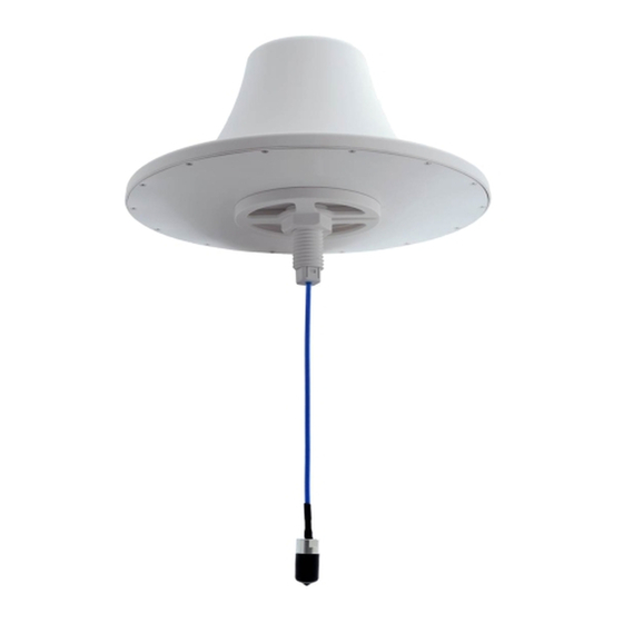
Figure 1
Patent Pending
Please read all instructions carefully before attempting to
install and use this product.
SAFETY
The CMS38606P and all associated equipment should be installed
in accordance with all applicable local and national electrical code
guidelines to ensure safe operation.
LOCATION
For the best results, mount the antenna near the center of the
coverage area. A line-of-sight path between the antenna and active
floor locations generally works best. Although microwave signals
penetrate cubical dividers and interior walls with little attenuation,
reinforced block attenuate signals or cause multipath, a condition
where reflected signals interfere with the primary signal path. Avoid
mounting next to a column or vertical support that could create a
''shadow zone'' of reduced coverage to one portion of the room.
PRECAUTION
For best PIM results:
1.
Make sure the connectors are clean and free from any
metal flakes/dirt & tighten the connectors using torque
wrench according to connector torque specification below.
Avoid extreme bending to the cable. Do not remove
2.
the dust cap from connectors when not in use.
STANDARD MOUNTING
A threaded post on the back of the antenna and a supplied
mounting nut are the primary mounting method when access is
available to both sides of the mounting surface, such as a
suspended ceiling tile. Mark the desired mounting location on the
tile and cut a ø40mm (1.57") hole for threaded post. Feed the
cables through the hole and secure the antenna with the mounting
nut. (See figure 1).
CMS38606P
ASSEMBLY INSTALLATION
INSTRUCTIONS
165-00177_AC
Advertisement

Subscribe to Our Youtube Channel
Related Manuals for Laird CMS38606P


Summary of Contents for Laird CMS38606P
- Page 1 Low Band Cellular (776-786MHz) High Band Cellular (1870-1910MHz) SAFETY Polarization Vertical The CMS38606P and all associated equipment should be installed Impedance 50Ω in accordance with all applicable local and national electrical code <-150dBc PIM, 3rd order, 2X20W guidelines to ensure safe operation.
- Page 2 CMS38606P ASSEMBLY INSTALLATION INSTRUCTIONS OPTIONAL MOUNTING Note: The optional mounting kits are NOT INCLUDED with the antenna; it needs to be purchased separately 165-00177_AC...
- Page 3 VSWR: V@380-520MHz, V@600-960MHz, V@1395-1435MHz, V@1690-6000MHz LOW PIM 380-520 MHz: -L dBc, 600-960 MHz: -L dBc, 1690-2700 MHz: -L dBc QR CODE: CMS38606P-XXX-SNYYWWZZZZ = SERIAL NUMBERING V = VALUE OF VSWR @ FREQUECY BANDS (380-520MHz, 600-960MHz, 1395-1435MHz, 1690-6000MHz). L = PIM Performance Level...
Need help?
Do you have a question about the CMS38606P and is the answer not in the manual?
Questions and answers