Advertisement
SPECIFICATIONS – Model Number AP-ANT-40
Frequency
Gain (dBi)
Port to Port Isolation
Nominal Impedance
Polarization
VSWR
Power Input (Max.)
Operating Temperature
Range
Connector
Exposed Cable length
Weight
Mounting
Ceiling mount (drywall or tile flush mount)
Radome
Dimensions, mm
RoHs
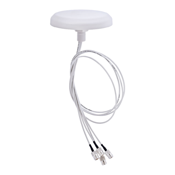
Figure 1
STANDARD MOUNTING
A threaded post on the back of the antenna and a supplied
mounting nut are the primary mounting method when access
is available to both sides of the mounting surface, such as a
suspended ceiling tile. Mark the desired mounting location on
the tile and cut a ø40mm (1.57") hole for threaded post. Feed
the cables through the hole and secure the antenna with the
mounting nut. (See figure 1).
2300-2700 MHz
4900‐6000 MHz
4.5 (typical), 5.0 (max) @ 2300 Band
3.7 (typical), 4.0 (max) @ 2700 Band
5.0 (typical), 6.0 (max) @ 4900 Band
5.0 (typical), 6.0 (max) @ 6000 Band
<‐16dB @ 2300‐2700 MHz
<‐20dB @ 4900‐6000 MHz
50 Ohms
Linear, Omnidirectional
1.5:1 typical (2.0:1 max)@ 2300 band
1.5:1 typical (2.0:1 max)@ 2700 band
1.5:1 typical (2.0:1 max)@ 4900 band
1.5:1 typical (2.0:1 max)@ 6000 band
10 Watts (ambient temp of 25°C)
‐40°C + 85°C
Model Specific
Model Specific
Approximately 0.45 kg
PC/ABS V‐0 (White)
178
mm (Dia.) x 32 mm (H)
Compliant
Omni‐Directional Ceiling Mount Antenna
ASSEMBLY AND INSTALLATION INSTRUCTIONS
Patent Pending
AP-ANT-40
Please read all instructions carefully before attempting to
install and use this product.
The AP-ANT-40 and all associated equipment should be installed in
accordance with all applicable local and national electrical code
guidelines to ensure safe operation.
APPLICATION
The AP-ANT-40 antenna is designed and optimized for WLAN
MIMO system requirements covering a wide range of operating
frequency. The covered frequency range includes the
band of 2300-2700/4900-6000 MHz. The antenna offers low cross
correlation between the four radiating elements suitable for MIMO
applications.
LOCATION
For best results, mount the antenna near the center of the coverage
area. A line‐of‐sight path between the antenna and active floor
locations generally works best. Although signals penetrate cubical
dividers and interior walls with little attenuation, reinforced block
walls, banks of metal cabinets, or steel shelving may attenuate
signals or cause multipath, a condition where reflected signals
interfere with the primary signal path. Avoid mounting next to a
column or vertical support that could create a "shadow zone" of
reduced coverage to one portion of the room.
PRECAUTION
1. Make sure the connectors are clean and free from any metal
flakes/dirt & tighten the connectors using torque wrench
according to connector torque specification below.
2.
Avoid extreme bending to the cables.
3.
During installation of the antenna, cables should not be
crossing one another.
4.
Do not remove the dust cap from connectors when not in used.
AP-ANT-40
2300-2700 / 4900-6000 MHZ
SAFETY
165-00231_AB
Advertisement
Table of Contents

Subscribe to Our Youtube Channel
Related Manuals for Laird AP-ANT-40


Summary of Contents for Laird AP-ANT-40
- Page 1 Connector Model Specific Exposed Cable length Model Specific SAFETY Weight Approximately 0.45 kg The AP-ANT-40 and all associated equipment should be installed in Mounting Ceiling mount (drywall or tile flush mount) accordance with all applicable local and national electrical code Radome PC/ABS V‐0 (White) guidelines to ensure safe operation.
- Page 2 165-00231_AB...
Need help?
Do you have a question about the AP-ANT-40 and is the answer not in the manual?
Questions and answers