Advertisement

S5750E-16(28)(52)F(C)(X)(-P)-SI(R2.0)
CHAPTER 1 INTRODUCTION ................................................... 1-1
.......................................................................................... 1-1
1.2.1 Product Overview .................................................................................... 1-1
1.2.2 Features and Benefits ............................................................................. 1-2
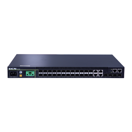
1.4.1 Front Panel ............................................................................................... 1-5
1.4.2 Back Panel ............................................................................................... 1-7
1.4.3 Status LEDs ............................................................................................. 1-7
1.4.4 Interface Description of Front Panel ..................................................... 1-9
CHAPTER 2 HARDWARE INSTALLATION ............................... 2-1
2.1.1 Environmental Requirements ................................................................ 2-1
2.1.2 Installation Notice ................................................................................... 2-4
2.1.3 Classs A Statement ................................................................................. 2-4
2.1.4 Security Warnings ................................................................................... 2-4
2.2.1 Verify the Package Contents .................................................................. 2-5
2.2.2 Required Tools and Utilities ................................................................... 2-5
2.3.1 Installing Switch ...................................................................................... 2-6
2.3.2 Connecting Console ............................................................................... 2-6
2.3.3 SFP Transceiver Installation .................................................................. 2-7
2.3.4 SFP+ extended module Installation ...................................................... 2-7
2.3.5 Copper Cable/Fiber Cable Connection ................................................. 2-8
2.3.6 AC Power Supply Connection ............................................................... 2-9
Content
................................................................ 1-1
.................................................................. 1-3
............................................................... 1-5
......................................................................... 2-1
............................................................... 2-5
........................................................................... 2-6
1
Content

Advertisement

Table of Contents
loading
Need help?

Need help?

Do you have a question about the S5750E-28C-SI and is the answer not in the manual?

Questions and answers

Summary of Contents for DCN S5750E-28C-SI

  • Page 1: Table Of Contents

    S5750E-16(28)(52)F(C)(X)(-P)-SI(R2.0) Content Content CHAPTER 1 INTRODUCTION ........... 1-1 1.1 O ..................1-1 VERVIEW 1.2 I ..............1-1 NTRODUCTION TO RODUCT 1.2.1 Product Overview ..................1-1 1.2.2 Features and Benefits ................1-2 1.3 P ..............1-3 HYSICAL PECIFICATIONS 1.4 D ............... 1-5 ESCRIPTION OF ARDWARE 1.4.1 Front Panel ....................
  • Page 2: Chapter 1 Introduction

    30W,24 ports simultaneously access single port average per port support power of 15.4W).S5750E-28X-P-SI supplies 20 copper ports+4 Combo ports+4 10Gb optical ports. S5750E-28C-SI supplies 24 copper ports+2 Combo ports+2 10Gb optical ports S5750E-52X-SI supplies 48 copper ports+4 10Gb optical ports, S5750E-28X-SI...
  • Page 3: Features And Benefits

    S5750E-28X-P-SI provides 20 fixed 1000Mb copper ports, 4 1000Mb COMBO ports (1000Mb fiber SFP ports/1000Mb copper ports) and 4 10Gb optical ports. S5750E-52X-SI provides 48 copper ports and 4 10Gb optical ports.S5750E-28C-SI provides 24 copper ports+2 Combo ports + 2 10Gb optical ports.S5750E-52X-SI provides 48 copper ports+4 10Gb optical ports.
  • Page 4: Physical Specifications

    S5750E-16(28)(52)F(C)(X)(-P)-SI(R2.0) Chapter 1 Introduction S5750E-16(28)(52)F(C)(X)(-P)-SI(R2.0) series switches fully support DiffServ Module. Each port provides 8 priority queues.Users can specify a queue bandwidth on each port. WRR/SP/SWRR scheduling also supported. S5750E-16(28)(52)F(C)(X)(-P)-SI(R2.0) series support the port trust. Users can configure trusted COS, DSCP, IP precedence and port priority. User can also modify packet’s DSCP and COS values.
  • Page 5 Support automatic timing 0℃~50℃ 0℃~50℃ Operating Temperature 5%~95% 5%~95% Relative Humidity Table 1-2 Physical Specifications Item S5750E-52X-SI S5750E-28C-SI 440×320×44 440×240×44 Dimension (W * H * D)(mm) Weight <6kg <6kg Fixed ports 48 100/1000Base-TX auto negotiation ethernet 24 100/1000Base-TX auto negotiation ethernet...
  • Page 6: Description Of Hardware

    S5750E-16(28)(52)F(C)(X)(-P)-SI(R2.0) Chapter 1 Introduction 0℃~50℃ 0℃~50℃ Operating Temperature 5%~95% 5%~95% Relative Humidity Table 1-3 Physical Specifications Item S5750E-28F-SI-R S5750E-16F-SI-R 440×240×44 330×230×44 Dimension (W * H * D)(mm) 3.85kg 2.5 kg Weight Fixed ports 8 1000Mb Combo ports 4 1000Mb Combo ports 16 1Gb optical ports 8 1Gb optical ports 4 10Gb optical ports...
  • Page 7 1 reset button and 1 Console port. Fig 1-3 Front Panel of S5750E-52X-SI S5750E-28C-SI Ethernet switches provide provide 24 100/1000Base-TX auto negotiation ehternet ports, 2 Combo ports,2 10Gb optical ports, 1 network management port, 1 USB interface, 1 reset button and 1 Console port.
  • Page 8: Back Panel

    S5750E-16(28)(52)F(C)(X)(-P)-SI(R2.0) Chapter 1 Introduction 1.4.2 Back Panel S5750E-28(52)C(X)(-P)-SI(R2.0) supplies 1 ground screw hole and 1 power plug-in interfaces. Fig 1-7 Back Panel of S5750E-28(52)C(X)(-P)-SI(R2.0) S5750E-28F-SI-R supplies 2 fans on the back panel. Fig 1-8 Back Panel of S5750E-28F-SI-R S5750E-16F-SI-R supplies 1 ground screw hole, 1 AC plug-in interface and 1 DC plug-in interface.
  • Page 9 S5750E-16(28)(52)F(C)(X)(-P)-SI(R2.0) Chapter 1 Introduction The other is system LEDs, they are used to show the work status of the system at the right of front panel. Table 1-6 S5750E-28(52)(C)(X)-SI(R2.0) System LEDs Panel Symbol Status Description PWR1 On (Green) Power1 is operating normally Power1 is not operating DIAG On(Green,...
  • Page 10: Interface Description Of Front Panel

    S5750E-16(28)(52)F(C)(X)(-P)-SI(R2.0) Chapter 1 Introduction MGMT On (Green) Network management port 10M / 100M / 1G is linking Network management port is not linking Blink Data forwarding 1.4.4 Interface Description of Front Panel S5750E-16(28)(52)F(C)(X)(-P)-SI(R2.0) series switches provide RJ-45 1000Mb copper port, interface of SFP+ 10Gb fiber transceivers and combo interface. Table 1-9 interface descriptions Interface mode Spec...
  • Page 11: Chapter 2 Hardware Installation

    S5750E-16(28)(52)F(C)(X)(-P)-SI(R2.0) Chapter 2 Hardware Installation Chapter 2 Hardware Installation 2.1 Installation Notice To ensure the proper operation for S5750E-16(28)(52)F(C)(X)(-P)-SI(R2.0) series and your physical security, please read carefully the following installation guide. 2.1.1 Environmental Requirements  The switch must be installed in a clean area. Otherwise, the switch may be damaged by electrostatic adherence.
  • Page 12 S5750E-16(28)(52)F(C)(X)(-P)-SI(R2.0) Chapter 2 Hardware Installation In addition, salt, acid and sulfide in the air are also harmful to the switch. Such harmful gases will aggravate metal corrosion and the aging of some parts. The site should avoid harmful gases, such as SO S, NO , NH and Cl...
  • Page 13 S5750E-16(28)(52)F(C)(X)(-P)-SI(R2.0) Chapter 2 Hardware Installation continued operation and an annual cumulative total of less than 15 days. Formidable operation conditions refers to the ambient temperature and relative humidity value that may occur during an air-conditioning system failure, and normal operation conditions should be recovered within 5 hours.
  • Page 14: Installation Notice

    S5750E-16(28)(52)F(C)(X)(-P)-SI(R2.0) Chapter 2 Hardware Installation The dimensions of the S5750E-16(28)(52)F(C)(X)(-P)-SI(R2.0) series is designed to be mounted on a standard 19’’ rack, please ensure good ventilation for the rack.  Every device in the rack will generate heat during operation, therefore vent and fans must be provided for an enclosed rack, and devices should not be stacked closely.
  • Page 15: Installation Preparation

    S5750E-16(28)(52)F(C)(X)(-P)-SI(R2.0) Chapter 2 Hardware Installation  Do not attempt to conduct the operations which can damage the switch or which can cause physical injury.  Do not install, move or disclose the switch and its modules when the switch is in operation.
  • Page 16: Installation Guide

    S5750E-16(28)(52)F(C)(X)(-P)-SI(R2.0) Chapter 2 Hardware Installation 2.3 Installation Guide 2.3.1 Installing Switch Fig 2-1 Install sketch map on the rack Please mount S5750E-16(28)(52)F(C)(X)(-P)-SI(R2.0) series on the 19’’ rack as below: 1. Attach the 2 brackets on the S5750E-16(28)(52)F(C)(X)(-P)-SI(R2.0) series with screws provided in the accessory kit. 2.
  • Page 17: Sfp Transceiver Installation

    S5750E-16(28)(52)F(C)(X)(-P)-SI(R2.0) Chapter 2 Hardware Installation Fig 2-2 Connecting Console to switch The connection procedure is shown below: Find the console cable provided in the accessory kit. Attach the Mini-USB end to console port of the switch. Connect the other side of the console cable to a character terminal (PC). Power on the switch and the character terminal.
  • Page 18: Copper Cable/Fiber Cable Connection

    S5750E-16(28)(52)F(C)(X)(-P)-SI(R2.0) Chapter 2 Hardware Installation S5750E-16(28)(52)F(C)(X)(-P)-SI(R2.0) series provide 10Gb slots. The procedure for installing the SFP+ 10Gb fiber transceiver is shown below: Step 1: Put on an ESD wrist strap (or antistatic gloves). Step 2: Insert the SFP+ transceiver to the 10G optical port. Do not put the SFP+ transceiver up-side-down.
  • Page 19: Ac Power Supply Connection

    S5750E-16(28)(52)F(C)(X)(-P)-SI(R2.0) Chapter 2 Hardware Installation Caution! Please verify the sign above the port to ensure using the other ports. Connecting to wrong ports might damage the transceiver or the other ports. When connecting other devices through a fiber cable to the switch, the output power of the fiber cable must not exceed the maximum received power of the corresponding modules.

Table of Contents

Save PDF