Table of Contents
Advertisement
DCRS-5960 Series Installation Guide
CHAPTER 1 INTRODUCTION .................................................... 1-1
.......................................................................................... 1-1
1.2.1 Product Overview ................................................................................. 1-1
1.2.2 Features and Benefits .......................................................................... 1-2
1.4.1 Front Panel ............................................................................................ 1-5
1.4.2 Back Panel ............................................................................................. 1-6
1.4.3 DC Power/PoE Power Input ................................................................. 1-7
1.4.4 Status LEDs ........................................................................................... 1-8
1.4.5 Interface Description of Front Panel ................................................. 1-11
1.4.6 MRS-2XFP/MRS-2SFP+ Extended Module Description ................... 1-12
CHAPTER 2 HARDWARE INSTALLATION ............................... 2-1
2.1.1 Environmental Requirements .............................................................. 2-1
2.1.2 Installation Notice ................................................................................. 2-4
2.1.3 Security Warnings ................................................................................ 2-4
2.2.1 Verify the Package Contents ................................................................ 2-5
2.2.2 Required Tools and Utilities ................................................................. 2-5
2.3.1 Installing Switch .................................................................................... 2-5
2.3.2 Connecting Console ............................................................................. 2-6
2.3.3 SFP Transceiver Installation ................................................................ 2-7
2.3.4 MRS-2XFP Extended Module Installation ........................................... 2-7
2.3.5 MRS-2SFP+ extended module Installation ......................................... 2-8
2.3.6 MRS-2GB Extended module Installation ............................................. 2-8
2.3.7 Copper Cable/Fiber Cable Connection ............................................... 2-9
2.3.8 AC Power Supply Connection ........................................................... 2-10
2.3.9 DC Power Supply Connection ........................................................... 2-10
2.3.10 PoE Power Supply Connection ........................................................ 2-11
Content
................................................................ 1-1
.................................................................. 1-3
............................................................... 1-5
......................................................................... 2-1
............................................................... 2-5
.......................................................................... 2-5
1
Content
Advertisement
Table of Contents

Related Manuals for DCN DCRS-5960-52T


Summary of Contents for DCN DCRS-5960-52T
-
Page 1: Table Of Contents
DCRS-5960 Series Installation Guide Content Content CHAPTER 1 INTRODUCTION ............ 1-1 1.1 O ..................1-1 VERVIEW 1.2 I ..............1-1 NTRODUCTION TO RODUCT 1.2.1 Product Overview ................. 1-1 1.2.2 Features and Benefits ................1-2 1.3 P ..............1-3 ... -
Page 2: Chapter 1 Introduction
44 fiber ports + 4 Combo ports + 2 DCRS-5960-52F-DC extended cards +DC power 1.2 Introduction to Product 1.2.1 Product Overview DCRS-5960 series switches include DCRS-5960-52T(R2), DCRS-5960-52T-DC(R2), DCRS-5960-52T-PoE(R2), DCRS-5960-28T(R2), DCRS-5960-28T-DC(R2), DCRS-5960-28T-PoE(R2), DCRS-5960-28F-DC and DCRS-5960-52F-DC switches. DCRS-5960-52T-DC(R2) and DCRS-5960-52T-PoE(R2) supply the consistent signal... -
Page 3: Features And Benefits
DCRS-5960 Series Installation Guide Chapter 1 Introduction interface with DCRS-5960-52T(R2), difference DCRS-5960-52T-DC(R2) implements 48V DC input, DCRS-5960-52T-PoE(R2) supplies 48 ports for exporting PoE power supply, and the max output power of each port is 15W. DCRS-5960-28T-DC(R2) DCRS-5960-28T-PoE(R2) supply consistent signal interface... -
Page 4: Physical Specifications
DCRS-5960 Series Installation Guide Chapter 1 Introduction switches to meet the requirements of complex network constructions. DCRS-5960 series switches support comprehensively ACL policies. The traffic can be classified by source/destination IP addresses, source/destination MAC addresses, IP protocols, TCP/UDP, IP precedence, time ranges and ToS. And various policies can be conducted to forward the traffic. - Page 5 DCRS-5960 Series Installation Guide Chapter 1 Introduction 440×324×44 440×324×44 440×324×44 440×324×44 440×324×44 440 × 324 × Dimension (W * H * D) (mm) Weight <6kg <6kg <6kg <6kg <6kg <6kg Fixed ports fiber fiber ports ports 100/1000Base- 100/1000Base- 100/1000Base- 100/1000Bas 1000Mb 1000Mb auto...
-
Page 6: Description Of Hardware
Fig 1-3 Front Panel of DCRS-5960-28T-PoE(R2) DCRS-5960-52T(R2) DCRS-5960-52T-DC(R2) DCRS-5960-52T-PoE(R2) Ethernet switches provide 44 100/1000Base-TX auto negotiation ehternet ports, 4 1000Mb Combo ports, 6 function LEDs and 1 Console port. Fig 1-4 Front Panel of DCRS-5960-52T(R2) Fig 1-5 Front Panel of DCRS-5960-52T-DC(R2) -
Page 7: Back Panel
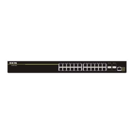
DCRS-5960 Series Installation Guide Chapter 1 Introduction Fig 1-6 Front Panel of DCRS-5960-52T-PoE(R2) DCRS-5960-28F-DC Ethernet switch provides 12 1000Mb fiber ports, 12 1000Mb Combo ports, 8 function LEDs and 1 Console port. Fig 1-7 Front Panel of DCRS-5960-28F-DC DCRS-5960-52F-DC ehternet switch provides 44 1000Mb fiber ports, 4 1000Mb Combo ports, 8 function LEDs and 1 Console port. -
Page 8: Dc Power/Poe Power Input
Chapter 1 Introduction 2 plug-in interfaces, 1 -48V DC input power interface, 1 input power interface of PoE and 1 220V input power interface. Fig 1-12 Back Panel of DCRS-5960-52T(R2) Fig 1-13 Back Panel of DCRS-5960-52T-DC(R2) Fig 1-14 Back Panel of DCRS-5960-52T-PoE(R2) DCRS-5960-28F-DC supplies 2 interfaces with the extended card, 1 interface with -48V DC power input and 1 interface with 220V AC power input. -
Page 9: Status Leds
DC power cathode input PIN3: -52V DC power cathode input PIN4: 0V DC power positive electrode input PIN5: 0V DC power positive electrode input 1.4.4 Status LEDs LEDs of DCRS-5960-28T(R2) / DCRS-5960-28T-DC(R2) / DCRS-5960-28T-PoE(R2) / DCRS-5960-52T(R2) / DCRS-5960-52T-DC(R2) / DCRS-5960-52T-PoE(R2) show the... - Page 10 Send or receive the data The other is system LEDs, they are used to show the work status of the system at the right of front panel. Table 1-3 DCRS-5960-28T(R2) / DCRS-5960-28T-DC(R2) / DCRS-5960-28T-PoE(R2) / DCRS-5960-52T(R2) / DCRS-5960-52T-DC(R2) / DCRS-5960-52T-PoE(R2) System LEDs Panel Status...
- Page 11 DCRS-5960 Series Installation Guide Chapter 1 Introduction LEDs of DCRS-5960-28F-DC / DCRS-5960-52F-DC show the corresponding state. There are two kinds of LEDs on front panel, one of its kinds is fiber/copper LEDs of port transceiver, they are at RJ45 linker or SFP linker. Each port of RJ45 linker corresponds a LED with double colors, each port of SFP linker corresponds two LEDs, detailed descriptions are shown in the following tables.
-
Page 12: Interface Description Of Front Panel
DCRS-5960 Series Installation Guide Chapter 1 Introduction System is operating normally On (Green) System is using DC power System does not use DC power On (Green) Port1 of M1 is at link state (Green, Port1 of M1 is receiving or sending M1-1 Blink) the data... -
Page 13: Mrs-2Xfp/Mrs-2Sfp+ Extended Module Description
DCRS-5960 Series Installation Guide Chapter 1 Introduction • SFP-SX-L transceiver 1000Base-SX SFP(850nm,MMF,550m) • SFP-LX-L transceiver 1000Base-LX SFP(1310nm, SMF, 10km or MMF, 550m) • SFP-LX-20-L transcever 1310nm lightwave, 9/125um single mode fiber: 20km • SFP-LX-40 transceiver 9/125um single mode fiber: 40km •... - Page 14 Figure 1-22 panel diagram of MRS-2GB Back panel diagrams of switch with extended modules are shown as follows: Figure 1-23 The back panel with extended modules for DCRS-5960-28T(R2) / DCRS-5960-52T(R2) Figure 1-24 The back panel with extended modules for DCRS-5960-28T-DC(R2) / DCRS-5960-52T-DC(R2)
- Page 15 DCRS-5960 Series Installation Guide Chapter 1 Introduction Figure 1-26 The back panel with extended modules for DCRS-5960-28F-DC / DCRS-5960-52F-DC Extended module‘s LED descriptions are in the following: Table 1-8 LED descriptions of 10Gb extended module Status Description Green Ports are at link state with 10G Link/Activity Blink(Green) Ports are at active state with 10G...
-
Page 16: Chapter 2 Hardware Installation
DCRS-5960 Series Installation Guide Chapter 2 Hardware Installation Chapter 2 Hardware Installation 2.1 Installation Notice To ensure the proper operation for DCRS-5960 series and your physical security, please read carefully the following installation guide. 2.1.1 Environmental Requirements The switch must be installed in a clean area. Otherwise, the switch may be damaged by electrostatic adherence. - Page 17 DCRS-5960 Series Installation Guide Chapter 2 Hardware Installation harmful gases will aggravate metal corrosion and the aging of some parts. The site should avoid harmful gases, such as SO S, NO , NH and Cl , etc. The table below details the threshold value.
- Page 18 DCRS-5960 Series Installation Guide Chapter 2 Hardware Installation may occur during an air-conditioning system failure, and normal operation conditions should be recovered within 5 hours. 2.1.1.3 Power Supply Before powering on the power supply, please check the power input to ensure proper grounding of the power supply system.
-
Page 19: Installation Notice
DCRS-5960 Series Installation Guide Chapter 2 Hardware Installation 19’’ rack, please ensure good ventilation for the rack. Every device in the rack will generate heat during operation, therefore vent and fans must be provided for an enclosed rack, and devices should not be stacked closely. When mounting devices in an open rack, care should be taken to prevent the rack frame from obstructing the switch ventilation openings. -
Page 20: Installation Preparation
DCRS-5960 Series Installation Guide Chapter 2 Hardware Installation power immediately. Caution! Potential risk include: Electric leakage, Power supply arcing, Power line breakage, Imperfect earth, Overload circuit and Electrical short circuit. If electric shock, fire, electrical short circuit occurs, please cut off the electricity supply and alarm rapidly. Rescue the injured person in the contingency under inherently safe, give the injured person proper first aid treatment according to the injury state, and seek help from the Medical Emergency using various ways. -
Page 21: Connecting Console
DCRS-5960 Series Installation Guide Chapter 2 Hardware Installation Fig 2-1 Install sketch map on the rack Please mount DCRS-5960 series on the 19’’ rack as below: 1. Attach the 2 brackets on the DCRS-5960 series with screws provided in the accessory kit. -
Page 22: Sfp Transceiver Installation
DCRS-5960 Series Installation Guide Chapter 2 Hardware Installation Fig 2-2 Connecting Console to switch The connection procedure is shown below: Find the console cable provided in the accessory kit. Attach the Mini-USB end to console port of the switch. Connect the other side of the console cable to a character terminal (PC). Power on the switch and the character terminal. -
Page 23: Mrs-2Sfp+ Extended Module Installation
DCRS-5960 Series Installation Guide Chapter 2 Hardware Installation DCRS-5960 series provide 10Gb slots. The procedure for installing the MRS-2XFP module and the XFP 10Gb fiber transceiver is shown below: Step 1: Put on an ESD wrist strap (or antistatic gloves). Step 2: Insert the MRS-2XFP module to the guide rail inside the 10Gb module slot. -
Page 24: Copper Cable/Fiber Cable Connection
DCRS-5960 Series Installation Guide Chapter 2 Hardware Installation Step 4: Insert the SFP transceiver to the guide rail inside the MRS-2GB. Do not put the SFP transceiver up-side-down. Step 5: Push the SFP transceiver along the guide rail gently until it comes into contact with the MRS-2GB. -
Page 25: Ac Power Supply Connection
DCRS-5960 Series Installation Guide Chapter 2 Hardware Installation ports might damage the transceiver or the other ports. When connecting other devices through a fiber cable to the switch, the output power of the fiber cable must not exceed the maximum received power of the corresponding modules. Otherwise, it will damage the fiber transceiver. -
Page 26: Poe Power Supply Connection
DCRS-5960 Series Installation Guide Chapter 2 Hardware Installation damaged or malfunction. Do not open the switch shell without permission. It can cause physical injury. 2.3.10 PoE Power Supply Connection When using PoE function of DCRS-5960 series, it needs to connect the external PoE power with 5 holes socket.
Need help?
Do you have a question about the DCRS-5960-52T and is the answer not in the manual?
Questions and answers