Table of Contents
Advertisement
Quick Links
Advertisement
Table of Contents

Subscribe to Our Youtube Channel
Related Manuals for Hirschmann iFLEX TRS 14


Summary of Contents for Hirschmann iFLEX TRS 14
- Page 1 iFLEX TRS 14 Transceiver for wireless sensors Contents Safety instructions Product description Installation Commissioning Configuration Service and maintenance Technical data User manual Issue A - 08/2010 This document has the order no. 21-810-19-0003_421830_en...
-
Page 2: Table Of Contents
Erasing the EEPROM .................31 Setting the angle range (angle sensor only)..........32 Service and maintenance ................33 Technical data....................34 © 2010 Hirschmann Automation and Control GmbH · Branch Office Ettlingen · E-mail: info.ecs@hirschmann.de 21-810-19-0003_421830_en (Rev A).doc / 2010-08-31 / Issue A / rk. - Page 3 Table 3 Overview of signal ranges ..............28 Figure 1: View of the iFLEX TRS 14..............12 Figure 2: Dimensions of the iFLEX TRS 14 (with magnetic base antenna) ..13 Figure 3: Magnetic base antenna (art. no.536023) with mounted radiator..14 Figure 4: Pin configuration of the central connector ..........
- Page 4 Introduction INTRODUCTION This manual is a component of the equipment or system supplied by Hirschmann Automation and About this manual Control GmbH. Keep this manual in a safe place and ensure that it is available to all users. The contents of this manual are subject to change. Hirschmann Automation and Control GmbH...
- Page 5 Usage instructions and information, but no dangerous situation. HINT Supplementary comments and recommendations for the user. © 2010 Hirschmann Automation and Control GmbH · Branch Office Ettlingen · E-mail: info.ecs@hirschmann.de 21-810-19-0003_421830_en (Rev A).doc / 2010-08-31 / Issue A / rk.
-
Page 6: Safety Instructions
• Hold the printed circuit board only by the edges • Do not touch components or connector pins or tracks © 2010 Hirschmann Automation and Control GmbH · Branch Office Ettlingen · E-mail: info.ecs@hirschmann.de 21-810-19-0003_421830_en (Rev A).doc / 2010-08-31 / Issue A / rk. - Page 7 Never clean the device with a high pressure cleaner! Have damage to the decorative foil repaired professionally without delay! © 2010 Hirschmann Automation and Control GmbH · Branch Office Ettlingen · E-mail: info.ecs@hirschmann.de 21-810-19-0003_421830_en (Rev A).doc / 2010-08-31 / Issue A / rk.
-
Page 8: Eu Conformity Declaration
Safety instructions 1.1 EU conformity declaration © 2010 Hirschmann Automation and Control GmbH · Branch Office Ettlingen · E-mail: info.ecs@hirschmann.de 21-810-19-0003_421830_en (Rev A).doc / 2010-08-31 / Issue A / rk. - Page 9 Safety instructions © 2010 Hirschmann Automation and Control GmbH · Branch Office Ettlingen · E-mail: info.ecs@hirschmann.de 21-810-19-0003_421830_en (Rev A).doc / 2010-08-31 / Issue A / rk.
-
Page 10: Product Description
The iFLEX TRS 14 is a transceiver for the wireless coupling of wireless sensors from the Hirsch- mann xSENS-xxx-W1 family. Up to 4 wireless sensors can be connected wirelessly to a single iFLEX TRS 14. The number of How many sensors can be connected? wireless sensors can be extended as required by the employment of several transceivers. -
Page 11: Product Features
(e.g. radio, TV, mobile telephone etc.) or close to power supply systems. 2.4 Scope of supply The scope of supply of the iFLEX TRS 14 with accessories (art. no. 608177) consists of the follow- ing parts: iFLEX TRS 14... -
Page 12: View Of Device
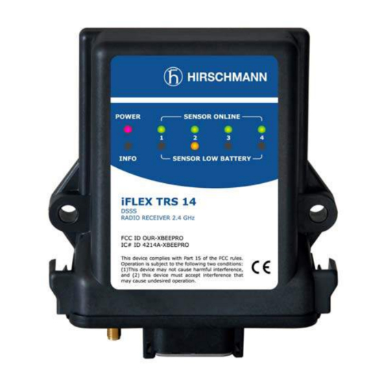
1 to 4 Coaxial socket Central plug for antenna Figure 1: View of the iFLEX TRS 14 © 2010 Hirschmann Automation and Control GmbH · Branch Office Ettlingen · E-mail: info.ecs@hirschmann.de 21-810-19-0003_421830_en (Rev A).doc / 2010-08-31 / Issue A / rk. -
Page 13: Dimensions
Product description 2.6 Dimensions Figure 2: Dimensions of the iFLEX TRS 14 (with magnetic base antenna) © 2010 Hirschmann Automation and Control GmbH · Branch Office Ettlingen · E-mail: info.ecs@hirschmann.de 21-810-19-0003_421830_en (Rev A).doc / 2010-08-31 / Issue A / rk. -
Page 14: Installation
3.1.1 iFLEX TRS 14 The iFLEX TRS 14 must be mounted in a suitable place on a sufficiently firm surface with the con- nections at the bottom. The device may be used both indoors and outdoors and is to be mounted such that the LEDs are visible. -
Page 15: Electrical Connection
The device may only be connected to a DC voltage source of 10 V to 30 V! © 2010 Hirschmann Automation and Control GmbH · Branch Office Ettlingen · E-mail: info.ecs@hirschmann.de 21-810-19-0003_421830_en (Rev A).doc / 2010-08-31 / Issue A / rk. -
Page 16: Wiring Of The Central Connector
The external screen should be connected if possible: Length: 4,7 m Figure 5: Wiring of the connecting cable © 2010 Hirschmann Automation and Control GmbH · Branch Office Ettlingen · E-mail: info.ecs@hirschmann.de 21-810-19-0003_421830_en (Rev A).doc / 2010-08-31 / Issue A / rk. -
Page 17: Commissioning
TRS14. 4.1 Switching the device on After wiring the iFLEX TRS 14, the device switches itself on as soon as the supply voltage is pre- How is the device switched on? sent. - Page 18 ‘hoist limit’. At the same time, the relay contact opens and there is no voltage at the signal lights up? output. The LED may also light up briefly after the iFLEX TRS 14 is switched on, until the radio link to the registered hoist limit switches has been established. If the LED remains lit, this means that the radio link to a registered wireless hoist limit switch is interrupted.
-
Page 19: Status Leds
(capacity < 6.5 %) Replace the batter- ies soon! Table 2 Overview of status LED © 2010 Hirschmann Automation and Control GmbH · Branch Office Ettlingen · E-mail: info.ecs@hirschmann.de 21-810-19-0003_421830_en (Rev A).doc / 2010-08-31 / Issue A / rk. -
Page 20: Opening/Closing The Housing
Commissioning 4.3 Opening/closing the housing It is necessary to open the housing of the iFLEX TRS 14 in order to configure the output signals and the radio link by means of the programming button and jumpers as described below. First of all, disconnect the device from the power supply by pulling out the central plug. - Page 21 (clearly audible Make sure that the foam strip is positioned as click at both sides). shown. © 2010 Hirschmann Automation and Control GmbH · Branch Office Ettlingen · E-mail: info.ecs@hirschmann.de 21-810-19-0003_421830_en (Rev A).doc / 2010-08-31 / Issue A / rk.
-
Page 22: Preconfiguration Of The Output Signals (Current/Voltage)
If you have configured the signal outputs as voltage outputs, it is also necessary to select the signal range. (See chapter 5.4) © 2010 Hirschmann Automation and Control GmbH · Branch Office Ettlingen · E-mail: info.ecs@hirschmann.de 21-810-19-0003_421830_en (Rev A).doc / 2010-08-31 / Issue A / rk. -
Page 23: Configuration
An overview of the functions that can be called via the programming button can be found below: © 2010 Hirschmann Automation and Control GmbH · Branch Office Ettlingen · E-mail: info.ecs@hirschmann.de 21-810-19-0003_421830_en (Rev A).doc / 2010-08-31 / Issue A / rk. -
Page 24: Overview Of Functions
A detailed description of the functions with which the device can be configured is provided below. © 2010 Hirschmann Automation and Control GmbH · Branch Office Ettlingen · E-mail: info.ecs@hirschmann.de 21-810-19-0003_421830_en (Rev A).doc / 2010-08-31 / Issue A / rk. -
Page 25: Registering A Wireless Sensor
TRS 14. Follow the procedure described below to register a wireless sensor. The wireless sensor should be no more than 1 metre away from the iFLEX TRS 14 during the registration phase. Connect the iFLEX TRS 14 to the power supply again. (See also Chapter 4.1) HINT Keep a fresh set of batteries at the ready for the registration. - Page 26 Online LED lights steadily (in this less sensor is now ready to be mounted. case e.g. channel 1). © 2010 Hirschmann Automation and Control GmbH · Branch Office Ettlingen · E-mail: info.ecs@hirschmann.de 21-810-19-0003_421830_en (Rev A).doc / 2010-08-31 / Issue A / rk.
-
Page 27: Deleting Wireless Sensors
Wireless sensors that are not to be used any longer must be deleted and deactivated by removing the batteries. Follow the procedure described below to delete a wireless sensor. Open the housing of the iFLEX TRS 14 as described in chapter 4.3. abmelden von Kanal 1 abmelden von Kanal 2... -
Page 28: Setting The Signal Range
Table 3 Overview of signal ranges 1 lb(US) = 0,453kg 1 mph = 1,61 km/h Conversion: © 2010 Hirschmann Automation and Control GmbH · Branch Office Ettlingen · E-mail: info.ecs@hirschmann.de 21-810-19-0003_421830_en (Rev A).doc / 2010-08-31 / Issue A / rk. - Page 29 Configuration Follow the procedure described below to set the signal range. Open the housing of the iFLEX TRS 14 as described in chapter 4.3. Auswahl Signalbereich A Auswahl Signalbereich B Auswahl Signalbereich C Auswahl Signalbereich D ▲ Press and hold the programming button of the iFLEX TRS14 until:...
-
Page 30: Adjusting The Zero Point (Load/Angle Sensor Only)
Follow the procedure described below in order to adjust the zero point. Open the housing of the iFLEX TRS 14 as described in chapter 4.3. abgleichen Sensor an Kanal 1 abgleichen Sensor an Kanal 2... -
Page 31: Erasing The Eeprom
Only use this function if you really want to delete all configuration data! Follow the procedure described below in order to erase the EEPROM: Open the housing of the iFLEX TRS 14 as described in chapter 4.3. EEProm löschen Winkelbereich -15...+15°... -
Page 32: Setting The Angle Range (Angle Sensor Only)
If an angle sensor is connected, this function is used to define the type of sensor being used. Follow the procedure described below in order to adjust the angle range. Open the housing of the iFLEX TRS 14 as described in chapter 4.3. EEProm löschen Winkelbereich -15...+15°... -
Page 33: Service And Maintenance
Service and maintenance 6 Service and maintenance The iFLEX TRS 14 transceiver does not contain any serviceable parts. The micro-fuse inside the device is self-resetting and therefore does not need to be exchanged. If you notice malfunctions, you should switch the device off and have it checked and, if necessary, repaired immediately by an authorised Hirschmann service partner. -
Page 34: Technical Data
- Antenna radiator 2.4 GHz band - Connecting cable, 4.5 m, partly prefabricated - User manual on CD © 2010 Hirschmann Automation and Control GmbH · Branch Office Ettlingen · E-mail: info.ecs@hirschmann.de 21-810-19-0003_421830_en (Rev A).doc / 2010-08-31 / Issue A / rk. - Page 35 Illustrations / Images Drawings, Diagrams Tables Did you discover errors in this manual? If so, on which side? © 2010 Hirschmann Automation and Control GmbH · Branch Office Ettlingen · E-mail: info.ecs@hirschmann.de 21-810-19-0003_421830_en (Rev A).doc / 2010-08-31 / Issue A / rk.
- Page 36 Hirschmann Automation and Control GmbH Documentation Hertzstr. 32-34 76275 Ettlingen / Germany Thank you ! © 2010 Hirschmann Automation and Control GmbH · Branch Office Ettlingen · E-mail: info.ecs@hirschmann.de 21-810-19-0003_421830_en (Rev A).doc / 2010-08-31 / Issue A / rk.
- Page 37 Notes © 2010 Hirschmann Automation and Control GmbH · Branch Office Ettlingen · E-mail: info.ecs@hirschmann.de 21-810-19-0003_421830_en (Rev A).doc / 2010-08-31 / Issue A / rk.
Need help?
Do you have a question about the iFLEX TRS 14 and is the answer not in the manual?
Questions and answers