Table of Contents
Advertisement
Quick Links
Advertisement
Table of Contents

Subscribe to Our Youtube Channel
Related Manuals for Hirschmann iFLEX TRS 10


Summary of Contents for Hirschmann iFLEX TRS 10
- Page 1 iFLEX TRS 10 CAN Transceiver for wireless sensors Contents Safety instructions Product description Installation Commissioning Service and maintenance Technical data Appendix User manual Issue B - 08/2011 This document has the order no. 21-810-19-0001_421826_en...
-
Page 2: Table Of Contents
Object listing table ..................23 Wiring of the adaptor cable for PCAN-USB..........25 List of tables and illustrations ..............25 © 2010 Hirschmann Automation and Control GmbH · Branch Office Ettlingen · E-mail: info.ecs@belden.com 21-810-19-0001_421826_en_Rev_B.doc / 2011-08-09 / Issue B / rk, kg. - Page 3 Made changes requested by HAC – Chambersburg Gase ECN 11-169 HIRSCHMANN Automation and Control GmbH Hertzstr. 32-34, 76275 Ettlingen, phone +49 (0)7243-709-0 © 2010 Hirschmann Automation and Control GmbH · Branch Office Ettlingen · E-mail: info.ecs@belden.com 21-810-19-0001_421826_en_Rev_B.doc / 2011-08-09 / Issue B / rk, kg.
-
Page 4: Installation
Introduction INTRODUCTION This manual is a component of the equipment or system supplied by Hirschmann Automation and About this manual Control GmbH. Keep this manual in a safe place and ensure that it is available to all users. The contents of this manual are subject to change. Hirschmann Automation and Control GmbH... - Page 5 Provides instructions for avoiding the possibly damaging situation. NOTE Usage instructions and information HINT Supplementary comments and recommendations for the user © 2010 Hirschmann Automation and Control GmbH · Branch Office Ettlingen · E-mail: info.ecs@belden.com 21-810-19-0001_421826_en_Rev_B.doc / 2011-08-09 / Issue B / rk, kg.
-
Page 6: Safety Instructions
The device must not be used in the direct proximity of radar systems or transmitters (e.g. radio, TV, mobile telephone etc.) or close to power supply systems. © 2010 Hirschmann Automation and Control GmbH · Branch Office Ettlingen · E-mail: info.ecs@belden.com 21-810-19-0001_421826_en_Rev_B.doc / 2011-08-09 / Issue B / rk, kg. -
Page 7: Eu Conformity Declaration
Safety instructions 1.1 EU conformity declaration © 2010 Hirschmann Automation and Control GmbH · Branch Office Ettlingen · E-mail: info.ecs@belden.com 21-810-19-0001_421826_en_Rev_B.doc / 2011-08-09 / Issue B / rk, kg. - Page 8 Safety instructions © 2010 Hirschmann Automation and Control GmbH · Branch Office Ettlingen · E-mail: info.ecs@belden.com 21-810-19-0001_421826_en_Rev_B.doc / 2011-08-09 / Issue B / rk, kg.
-
Page 9: Product Description
The iFLEX TRS 10 is a transceiver for the use of wireless sensors from the Hirschmann xSENS- xxx-W1 family to a CAN bus. Up to 4 wireless sensors can be connected wirelessly to a single iFLEX TRS 10. The number of How many sensors can be connected? wireless sensors can be extended, as required, by using several transceivers. -
Page 10: Product Features
2.3 Use for the intended purpose The iFLEX TRS 10 is a transceiver used for the transmission of wireless sensor data to a CAN bus using the CANopen protocol. Since impairment of the radio communication/range can occur, the device must not be used in close proximity to antenna systems with a high HF transmission power (e.g. -
Page 11: View Of Device
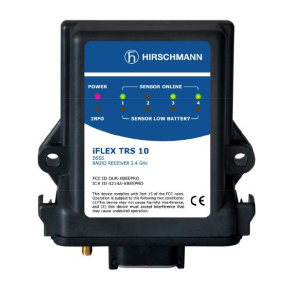
1 to 4 Coaxial socket Central plug for antenna Figure 1: View of the iFLEX TRS 10 © 2010 Hirschmann Automation and Control GmbH · Branch Office Ettlingen · E-mail: info.ecs@belden.com 21-810-19-0001_421826_en_Rev_B.doc / 2011-08-09 / Issue B / rk, kg. -
Page 12: Dimensions
Product description 2.6 Dimensions Figure 2: Dimensions of the iFLEX TRS 10 (with magnetic base antenna) © 2010 Hirschmann Automation and Control GmbH · Branch Office Ettlingen · E-mail: info.ecs@belden.com 21-810-19-0001_421826_en_Rev_B.doc / 2011-08-09 / Issue B / rk, kg. -
Page 13: Installation
3.1.1 iFLEX TRS 10 The iFLEX TRS 10 must be mounted in a suitable place on a sufficiently firm surface with the con- nections at the bottom. The distance between the holes in the housing is 102 mm. -
Page 14: Electrical Connection
After laying the cable, connect the coaxial connector of the antenna to the antenna socket on the Where is the antenna underside of the iFLEX TRS 10 or connect the antenna directly to the base of the TRS 10. Screw connected? the connector on hand tight. -
Page 15: Wiring Of The Central Connector
Please refer to the following illustration for the wiring of the connecting cable (article no. 536025): Length: 0,6 m Figure 6: Wiring of the CAN connecting cable © 2010 Hirschmann Automation and Control GmbH · Branch Office Ettlingen · E-mail: info.ecs@belden.com 21-810-19-0001_421826_en_Rev_B.doc / 2011-08-09 / Issue B / rk, kg. -
Page 16: Commissioning
4 Commissioning At least one functional wireless sensor must be available in order to commission and operate the system. A guide to commissioning the iFLEX TRS 10 and connecting the wireless sensors is provided be- low. 4.1 Adding a Wireless Sensor First, open the battery compartment of the wireless sensor after undoing the 4 screws and remove the batteries as shown in Figure 7. - Page 17 1 is now consistently lit and no longer flashing. If this is true, then your wireless sensor has successfully connected to the TRS 10. © 2010 Hirschmann Automation and Control GmbH · Branch Office Ettlingen · E-mail: info.ecs@belden.com 21-810-19-0001_421826_en_Rev_B.doc / 2011-08-09 / Issue B / rk, kg.
- Page 18 Note: If a sensor does not successfully connect, remove its batteries, wait 15 seconds and then follow steps 4 through 6. © 2010 Hirschmann Automation and Control GmbH · Branch Office Ettlingen · E-mail: info.ecs@belden.com 21-810-19-0001_421826_en_Rev_B.doc / 2011-08-09 / Issue B / rk, kg.
-
Page 19: Status Leds
(Capacity less than 6.5%) Replace the batter- ies soon! Table 2 Overview of status LED © 2010 Hirschmann Automation and Control GmbH · Branch Office Ettlingen · E-mail: info.ecs@belden.com 21-810-19-0001_421826_en_Rev_B.doc / 2011-08-09 / Issue B / rk, kg. -
Page 20: Troubleshooting
Commissioning 4.3 Troubleshooting After wiring the iFLEX TRS 10, the device switches itself on as soon as a supply voltage is present How is the device switched on? on the CAN bus. After switching on, the system begins with a self-diagnostic routine. -
Page 21: Service And Maintenance
Service and maintenance Service and maintenance The iFLEX TRS 10 contains no serviceable parts and may therefore not be opened. The fuse in- side the device is self-resetting and therefore does not need to be exchanged. If you notice mal-... -
Page 22: Technical Data
- Antenna radiator 2.4 GHz - Connecting cable, 0.6 m, fully prefabricated - T-piece for CAN bus - User manual © 2010 Hirschmann Automation and Control GmbH · Branch Office Ettlingen · E-mail: info.ecs@belden.com 21-810-19-0001_421826_en_Rev_B.doc / 2011-08-09 / Issue B / rk, kg. -
Page 23: Appendix
3rd object = 3rd analog input, 16 bit resolution 0x04 0x6401 04 10 4th object = 4th analog input, 16 bit resolution © 2010 Hirschmann Automation and Control GmbH · Branch Office Ettlingen · E-mail: info.ecs@belden.com 21-810-19-0001_421826_en_Rev_B.doc / 2011-08-09 / Issue B / rk, kg. - Page 24 Analog value 2nd analog channel 0x03 Analog value 3rd analog channel 0x04 Analog value 4th analog channel © 2010 Hirschmann Automation and Control GmbH · Branch Office Ettlingen · E-mail: info.ecs@belden.com 21-810-19-0001_421826_en_Rev_B.doc / 2011-08-09 / Issue B / rk, kg.
-
Page 25: Wiring Of The Adaptor Cable For Pcan-Usb
Table 2 Overview of status LED ................19 Figure 1: View of the iFLEX TRS 10..............11 Figure 2: Dimensions of the iFLEX TRS 10 (with magnetic base antenna) ..12 Figure 3: Short, direct connection antenna............13 Figure 4: Magnetic base antenna (art. no.536023) with mounted radiator..13 Figure 5: Pin configuration of the central connector .......... - Page 26 Appendix © 2010 Hirschmann Automation and Control GmbH · Branch Office Ettlingen · E-mail: info.ecs@belden.com 21-810-19-0001_421826_en_Rev_B.doc / 2011-08-09 / Issue B / rk, kg.
- Page 27 Did you discover errors in this manual? If so, in which section number or which part of the manual? © 2010 Hirschmann Automation and Control GmbH · Branch Office Ettlingen · E-mail: info.ecs@belden.com 21-810-19-0001_421826_en_Rev_B.doc / 2011-08-09 / Issue B / rk, kg.
- Page 28 Hirschmann Automation and Control GmbH Documentation Hertzstr. 32-34 76275 Ettlingen / Germany Thank you ! © 2010 Hirschmann Automation and Control GmbH · Branch Office Ettlingen · E-mail: info.ecs@belden.com 21-810-19-0001_421826_en_Rev_B.doc / 2011-08-09 / Issue B / rk, kg.
- Page 29 Notes © 2010 Hirschmann Automation and Control GmbH · Branch Office Ettlingen · E-mail: info.ecs@belden.com 21-810-19-0001_421826_en_Rev_B.doc / 2011-08-09 / Issue B / rk, kg.
Need help?
Do you have a question about the iFLEX TRS 10 and is the answer not in the manual?
Questions and answers