Table of Contents
Advertisement
This manual is an integral part of the system approval and the extinguisher must be
installed and maintained in accordance with all listed requirements.
Read and comply with these instructions, warnings and limitations before installing.
FG Models:
FD Models:
HFC 227ea
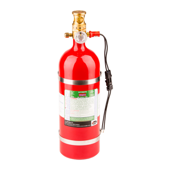
Model FG and FD Fire Extinguishers
Installation Instructions
Owner's Manual
U.S. Coast Guard Approved / FM Approved
No. 162.029 / 237 / 0
Suitable for use on:
0F (-18C) to 130F (54C)
20F (-7C) to 130F (54C)
Always maintain this owner's manual
nearby for operator reference.
Metalcraft Inc.
Sea-Fire Marine Products
9351-G Philadelphia Rd.
Baltimore, MD 21237
Tel: +1 410-687-5500
Fax: +1 410-687-5503
Owner's Manual PN: 123-194, Revision F
Printed in the USA
Advertisement
Table of Contents

Related Manuals for Sea-Fire FG 25-75


Summary of Contents for Sea-Fire FG 25-75
- Page 1 0F (-18C) to 130F (54C) FD Models: 20F (-7C) to 130F (54C) Always maintain this owner’s manual nearby for operator reference. Metalcraft Inc. Sea-Fire Marine Products 9351-G Philadelphia Rd. Baltimore, MD 21237 Tel: +1 410-687-5500 Fax: +1 410-687-5503 Owner’s Manual PN: 123-194, Revision F...
-
Page 2: Warnings
WARNING CONCENTRATED AGENT AND BY-PRODUCT OF APPLICATION TO FIRE ARE TOXIC. AVOID BREATHING OF FUMES OR PROLONGED EXPOSURE. ACCIDENTAL DISCHARGE DURING HANDLING OR INSTALLATION MAY CAUSE SERIOUS INJURY. BEFORE ATTEMPTING TO INSTALL THIS DEVICE, READ AND COMPLY WITH INSTRUCTIONS, WARNINGS, AND LIMITATIONS CONTAINED IN THIS MANUAL. DO NOT LIFT, CARRY OR HANDLE BY SENSOR VALVE / DETECTOR. -
Page 3: Table Of Contents
Index Section Page(s) Warnings Application/Limitations System Operations Supervisory Pressure Switch System Status Indicator Light Pressure Relief Assembly (Burst Disk) Interaction with Engines, Generators, and Powered Ventilation (Blowers) Diesel Engines or Generators, Powered Ventilation (Blowers) Gasoline Engines or Generators Installation Cylinder Cable Assembly Indicator Light System Maintenance... - Page 4 Sea-Fire “FG” and “FD” series have passed a rigid testing program and carry a FM Approvals and United States Coast Guard (USCG) approval for fire suppression applications in marine pleasure craft, un-inspected vessels, and Subchapter “T”...
- Page 5 MEC values equal to or below 6.7% for HFC-227ea may be protected by Sea-Fire “FG” and “FD” systems. The specification table in this manual lists the minimum and maximum approved compartment volume (size) allowable for each model (per NFPA 2001, UL 2166, FM 5600*).
- Page 6 Check the specification table for proper application before making installation. Sea-Fire Marine offers all models compliant to applicable European Directives. Systems will be shipped as requested. For orders requested compliant to CE directives, a Declaration of Conformance (DOC) shall be included.
-
Page 7: System Operations
System Operations Sea-Fire units described in this manual are automatically actuated by a temperature sensitive UL listed glass bulb tested in accordance with UL 199. These bulbs are manufactured and tested to be activated at a minimum temperature. FG 25 – 75 models: 200°F 93°C) when immersed in a liquid bath or approximately 250°F (121°C) when tested using an air bath. -
Page 8: Supervisory Pressure Switch
All Sea-Fire pre-engineered fire suppression systems approved for marine applications are packaged with an indicator light and faceplate. The indicator light (unless replaced by another Sea-Fire device: i.e.: display panel) must be installed for system supervision and operator awareness. When properly installed, activation of electrical power to the system will illuminate the light indicating normal charge condition. -
Page 9: Pressure Relief Assembly (Burst Disk)
Interaction with Engines, Generators and Powered Ventilation (Blowers) Sea-Fire offers optional engine interrupt systems which will automatically shut down engines, generators and powered ventilation upon discharge of the fire suppression system. They are available with 4, 6 or 8 control circuits and operate between 9 – 32 VDC. -
Page 10: Installation
Cable Assembly, SMAC, XX ft: Bidirectional Pull with Manual / Auto Face Plate and Fire Resistant Sleeve Only Sea-Fire cables are authorized for use with Sea-Fire suppression systems. Sea-Fire cables are offered in lengths from 4 feet to 100 feet. -
Page 11: Cylinder
I. Cylinder Installation: Step 1 Carefully remove cylinder from carton and visually check for damage in shipment. Step 2 To ensure that the cylinder is operational, both the weight and pressure indicator must conform with the cylinder specification as shown on the nameplate. - Page 12 Figure 1 MODELS FG 25 - 240 AND FD 150 – FD 1000 MAY BE INSTALLED HORIZONTAL OR VERTICAL. Horizontal or Models FD 150 Vertical Through 1000 and FG 25 Through 240 Mounting May Be Mounted Vertical or Horizontal Models FD 1025 <90°...
-
Page 13: Cable Assembly
Step 5 Locate bracket in desired position (Vertical-sensor Valve / Detector Head Up, or Horizontal, Figure 2). Ensure bulkhead or mounting surface is solid enough to hold the weight of the unit. Fasteners are not included. Use medium strength (Grade 5, Property Class 8.8) or better grade material. Use minimum 5/16”... - Page 14 Use extreme care when bending cable to avoid kinking. Selection of the correct size Sea-Fire cable length will reduce excess cable coil. d. Position the cable in its routing, but do not secure at this time. Steps 3A thru 3F must be completed prior to securing cable in its final location.
- Page 15 Using the manual discharge faceplate (Figure 3) as a template, mark and drill a 13/32inch (10.4 mm) hole. b. Remove the protective backing from the faceplate. While aligning the holes, place even pressure upon the faceplate. To insure a good bond, the temperature should be in excess of 50°F (10°C).
- Page 16 Pull on the cylinder (S-hook) end of the cable to retract the handle into the Ferrule. It may be necessary to softly push on the T-handle at the same time to seat the O-ring. Align the cross holes in the T-Handle and Ferrule and insert the safety pin through both items so that the end of the safety pin shows out the far side of the Ferrule.
- Page 17 NFPA 12A - Operating devices. Para. 1-8.3.7 maximum of 40 lb of force required at T handle (pull station) to activate system discharge. Sea-Fire - minimum of 10 lb of force required at the S hook (extinguisher) to activate system discharge. Test Procedure...
- Page 18 ii. If greater than 40 Ib of force was exerted to achieved 10 lb, the cable routing should be inspected and likely changed. Repeat inspection. Remove both scales. Pull on the S-Hook at the cylinder to retract the cable. Reinstall safety pin and confirm that release handle is now locked in place. Attach the tamper resistant round plastic tie to the safety pin by passing tie through the safety pin ring and around the cable assembly.
- Page 19 Using care, remove the factory installed actuator lever safety pin from the cylinder and store it in the nylon retainer provided on the cylinder neck (Figure 6-I). The Sea-Fire manual / automatic extinguisher is now fully operational. CAUTION: ALWAYS INSTALL SAFETY PIN IN CYLINDER ACTUATOR LEVER [FIG 6-A] WHEN PERFORMING SERVICE OR MAINTENANCE ON SYSTEM.
- Page 20 Carefully Insert “S” Release Hook into Bracket Release Cylinder Safety Head Pin is Located in Center Position Fig 6-A Fig 6-B Lock Cable in Place with Hairpin Cotter Pin Fig 6-D Fig 6-C Locate Pin Release Arm Behind Release Arm as a Backstop in Farthest Hole from...
- Page 21 Hairpin Actuator Lever Cotter Pin Actuator Hairpin Lever Cotter Pin Safety Pin Nylon Nylon Retainer Retainer Left Hand Pull Release Bracket Right Hand Pull Release Bracket Figure 6-G Figure 6-H Safety Pin Stored in Nylon Retainer Figure 6-I Reminder: Always install safety pin in cylinder actuator lever (Figure 6-A, 6-G and 6-H) when performing service or maintenance on system.
-
Page 22: Indicator Light
Direct Current Electrical System on Boats, copies of which may be obtained from ABYC, Edgewater, MD, USA, 21037, +1 (410) 956-1050. Supplies, which are not included with your Sea-Fire system and should be at hand before the indicator light installation, are as follows: 1. -
Page 23: System Maintenance
The following instructions are according to applicable regulatory agencies. These regulations change periodically and may be different from rules in place when this system and manual were shipped. Confirm requirements with Sea-Fire, local authorities having jurisdiction or applicable agency. All inspections must be performed by an authorized/Qualified inspector (Current RIN for DOT) and other requirements per local authorities as applicable. - Page 24 Models FD 150 – 1000 built with DOT 3AL/TC-3ALM cylinders and FD Models 1025 – 1500 built with DOT 4BW/TC 4BWM welded steel cylinders: Both of these cylinder types are reusable and must be periodically tested and re- qualified. The periodic inspection interval for both DOT 3AL and DOT 4BW cylinders filled as a Fire suppression system with the agent as supplied is 12 years from the date stamped on the cylinder.
-
Page 25: Agent Weight Inspection
Models FD 150 – 1500 with EC approval are designated as “CE” marked in accordance with the Pressure Equipment Directive (PED) 2014/68/EU. These systems are refillable. FD 150 – 1000 have seamless aluminum cylinders built to technical standards either BS EN 1975 or ISO 7866. Systems with π marked cylinders built to ISO standard 7866 are to be maintained in accordance with ISO 10461, Gas Cylinders –... -
Page 26: Pressure Gauge Inspection
Pressure Gauge Inspection Frequently check gauge for proper pressure, (every 6 months, minimum). Reading the Pressure Gauge (Inspection) The green section of the gauge is designed to show proper filling and pressurization at 70°F (21°C). Per applicable design standards, this is defined as ± 10% of nominal fill pressure. - Page 27 Pressure/Temperature Graphs for HFC-227ea, nominal at 70°F PN: 123-194, Rev. F Page 27 of 44...
-
Page 28: Indicator Light Inspection
Manual 123-253 is available to these individuals. Sea-Fire has an Installation checklist number 100-001 referenced in the Appendix of this manual. This may be used as a guide however it is not required for Sea-Fire. PN: 123-194, Rev. F Page 28 of 44... -
Page 29: Specification Tables
Specification Table Sea-Fire “FG” Series Automatic Fire Extinguishers Man / ft³ m³ Auto Auto Range Range FG 25A FG 25M 22-25 0.62-0.7 0.43 0.50 11.9 FG 50A FG 50M 30-50 0.85-1.4 0.58 1.00 FG 75A FG 75M 51-75 1.4-2.1 1.00 1.50... - Page 30 Specification Table Sea-Fire “FD” Series Automatic Fire Extinguishers Minimum HFC- Maximum HFC- Cylinder FD Model Volume of Protection Installation Dimension Requirements 227 ea 227 ea Diameter Man / ft³ m³ Auto Auto Range Range FD 150A FD 150M 126-150 3.5-4.2 19.9...
-
Page 31: Warranty
Any system found to be defective during the warranty period will repaired if possible, or replaced free of charge if classified as non-refillable (according to the product label) upon the prepaid return of the defective system to Sea-Fire facility or authorized service party. Proof of purchase required, otherwise date of manufacturer on extinguisher specification label will apply. - Page 32 Out of Warranty Replacements / Recharges Sea-Fire “FG” Model Series cylinders comply with US DOT Specification 39 and PED. These cylinders are not refillable. The discharge cylinder will be replaced with a comparable Sea-Fire extinguisher upon prepaid return of the discharged system for one-half of the current suggested list price.
- Page 33 PN: 123-194, Rev. F Page 33 of 44...
- Page 34 PN: 123-194, Rev. F Page 34 of 44...
- Page 35 PN: 123-194, Rev. F Page 35 of 44...
- Page 36 PN: 123-194, Rev. F Page 36 of 44...
- Page 37 PN: 123-194, Rev. F Page 37 of 44...
- Page 38 PN: 123-194, Rev. F Page 38 of 44...
- Page 39 PN: 123-194, Rev. F Page 39 of 44...
- Page 40 PN: 123-194, Rev. F Page 40 of 44...
- Page 41 PN: 123-194, Rev. F Page 41 of 44...
- Page 42 PN: 123-194, Rev. F Page 42 of 44...
- Page 43 PN: 123-194, Rev. F Page 43 of 44...
- Page 44 Sea-Fire Marine - USA Sea-Fire Europe, LTD Baltimore, Maryland Hampshire www.Sea-Fire.com United Kingdom www.Sea-Fire.co.uk PN: 123-194, Rev. F Page 44 of 44...
Need help?
Do you have a question about the FG 25-75 and is the answer not in the manual?
Questions and answers