Table of Contents

Related Manuals for Makeblock Airblock


Summary of Contents for Makeblock Airblock
- Page 1 Makeblock Co., Ltd. Address: 4th Floor, Building C3, Nanshan iPark, No.1001 Xueyuan Avenue, Nanshan District, Shenzhen, Guangdong Province, China Technical support: support@makeblock.com www.makeblock.com @Makeblock D1.4.6_7.40.4602...
- Page 2 Modular&Programmable Drone USER MANUAL...
-
Page 3: Table Of Contents
Table of Contents Software Download Introduction to Stickers Parts List User Guide to Aircraft Mode ·Operating Environment ·Warning ·Installation Steps ·Control Introduction to Main Control Module User Guide to Hovercraft Mode ·Operating Environment •Warning ·Installation Steps ·Control Introduction to Battery User Guide to Custom Mode ·Operating Methods ·Operating Environment ·Warning ·Programming... -
Page 4: Software Download
Software Download A tablet or smartphone is required to control the Airblock. Download from App Store Search "Makeblock" and install the application from app store. Download from Official Website http://learn.makeblock.com/en/software/ Login to download the corresponding version. System and Device Requirements For iOS Devices: Requires iOS 9.0 or later versions. -
Page 5: Parts List
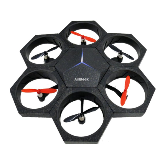
Parts List Battery Main Control Module Charger Charging Cable Power Modules Hovercraft Base Protective Cover... - Page 6 User Guide to Aircraft Mode The main control module includes 6 power module plug- in sockets, 3 LEDs, an ultrasonic sensor, a barometer, a gyroscope, Bluetooth, a microcontroller chip, etc. Front View Ultrasonic sensor is used for distance measurement. Works together with barometer to measure height change of the aircraft.
- Page 7 Battery Airblock does not have a power switch. When a fully charged Battery battery is inserted into the main controller, the controller automatically enters standby mode. When inserting battery into main control module or battery charger, please ensure that the contact points are placed in the correct direction.
- Page 8 Power Module Introduction to structure The Power Module includes a motor, a propeller, a plug, a Foot Pad Frame frame, etc. LED is installed on the frame. LED lights up when the motor is activated. Motor LED on aircraft front power module and foot pad are red. Foot pads on other power modules are black.
- Page 9 Power Module Introduction to Operating Principles In order to offset the self-rotation of the aircraft, the propellers are classified in red (counter-clockwise Direction of thrust Direction of thrust rotation) and black (clockwise rotation). Motors are also classified as clockwise and counter-clockwise rotation. Clockwise Rotation Counter-clockwise rotation...
- Page 10 Power Module Installation Angle Each power module may be installed onto its corresponding port on the main control module at 4 different angles. 180° 90° 270° Standard Angle...
- Page 11 Power Module Port Numbers The power modules of red propellers are connected to Ports 1, 3, 5 respectively, with the front module to Port 1. Connect the power modules of black propellers to Ports 2,4,6.
- Page 12 Stickers Fuselage Stickers Power Module Stickers Hovercraft Stickers...
- Page 13 Power Module Stickers: Attached to power module side in order to distinguish the direction of Airblock during flight. It is recommended to attach a red sticker to the aircraft front power module (Position 1) and a green sticker to the black propeller power module (Positiotn 4).
-
Page 14: User Guide To Aircraft Mode
User Guide to Aircraft Mode... -
Page 15: Operating Environment
Aerobatic flight needs a lager space in order to aviod collisions. High speed rotating motors and propellers may cause injury. Please keep a safety distance from the aircarft before operating Airblock. Dust, hair, fur, or water trapped in Airblock may result in motor malfunction or damage to electronic parts. -
Page 16: Installation Steps
User Guide to Aircraft Mode Installation Step 1 Installing the aircraft front power module Install aircraft front power module with red foot pad onto Port 1 of the main control module. Warning: If the front module is installed improperly, the direction of flight can not be controlled properly. - Page 17 User Guide to Aircraft Mode Installation Step 2 Install other power modules Install the remaining power modules in sequence onto the main control module.
- Page 18 User Guide to Aircraft Mode Installation Step 3 Battery Installation After a fully charged battery is inserted, Airblock will be automatically turned on and enters the standby mode. Direction of battery The LED on the main control module top will display a contact points white light.
-
Page 19: Control
Follow the instructions on the first page of User Guide to download and install the application. Step 1 Open the Makeblock application and move the tablet or smartphone close to the running Airblock, Bluetooth connection should be paired. Enter the control interface after successful connected. (Note: interface or icons may vary after software updates. -
Page 20: User Guide To Hovercraft Mode
User Guide to Hovercraft Mode... -
Page 21: Operating Environment •Warning
High speed rotating motors and propellers may cause injury. Please keep a saftety distance from the aircarft before operating Airblock. Dust, hair, fur, or water trapped in Airblock may result in motor malfunction or damage to electronic parts. Hovercraft must be installed correctly under user manual before operating on the water. -
Page 22: Installation Steps
User Guide to Hovercraft Mode Installation Step 1 Battery Installation Direction of battery contact points... - Page 23 User Guide to Hovercraft Mode Installation Step 2 Install the protective cover The protective covers must be installed in Hovercraft mode to protect the propellers and prevent the propellers from causing damage. The protective covers of Port1 and 4 are required only on the top side of the power modules.
- Page 24 User Guide to Hovercraft Mode Installation Step 3 Connect the front power module and a black propeller power module to Port 1 and 4 on the main control module respectively.
- Page 25 User Guide to Hovercraft Mode Installation Step 4 After connecting power modules to the main control module, fit the main control module onto the hovercraft hull. Warning: Port 1 faces forwards (the smaller end of the hull is the bow) The main control module must be installed in the correct direction, or it will not be able to control the direction of the hovercraft.
- Page 26 User Guide to Hovercraft Mode Installation Step 5 Protective covers are required on both top and bottom sides of other power modules. There are two types of protective covers; Pay attention to their difference during installation. Bottom...
- Page 27 User Guide to Hovercraft Mode Installation Step 6 After fitting the protective covers, attach the 4 power modules onto the main control module according to directions indicated in the diagram below. Check if the protective covers are fitted in the accurate places and if the power modules are attached securely to the main control module.
-
Page 28: Control
Follow the instructions on the first page of User Guide to download and install the application. Open the Step 1 Makeblock application and move tablet or smartphone within close distance to running Airblock, Bluetooth connection should be paired. Enter the hovercraft control interface after successful connection. (Choose Land or Water Mode according to the corresponding environment. -
Page 29: User Guide To Custom Mode
User Guide to Custom Mode Operating Methods Based on your own ideas, you can mount the power modules at different angles as either propellers or air-blowers. Programming different rotational velocities of motors can achieve corresponding airflow velocities and thrusts in different directions. - Page 30 Keep a distance of at least 2 meters from people or animals before running Airblock. High speed rotating motors and propellers may cause injury. Please keep a safety distance from the aircarft before operating Airblock. Dust, hair, fur, or water trapped in Airblock may result in motor malfunction or damage to electronic parts.
- Page 31 Step 2 Tap on the "New Project" option and select "Customize" to create a new controlling program for Airblock In "DESIGN" mode, drag and drop required keys modules into the edit area on the right. Tap on the module to Step 3 enter the "Code"...
- Page 32 Troubleshooting Propellers are not spinning Direction is incorrect Poor connection Aircraft head module is installed in the wrong position 1. Check if the connection of the power module and the main 1. When in Aircraft mode, if you have problems in controlling control module is too widely-spaced, connection is uneven, the direction, check if the aircraft front power module with or foreign matter is present.
- Page 33 Common Problems Power supply LED does not light up Fail to take off Battery has no power Power supply is insufficient Try again after charging battery for half an hour or longer. After successful connection to the application, you may check the power supply level in the control interface.
- Page 34 Common Problems Firmware upgrade To optimize user experience, Makeblock will continue to upgrade the software. After connecting to the Bluetooth device, you can click the setting icon on the upper left corner of the application. Select firmware information to view the current firmware version of the device.
- Page 35 The device has been evaluated to meet general RF exposure requirement. The device can be used in portable exposure condition without restriction. DECLARATION OF CONFORMITY Declaration of conformity Hereby, Makeblock Co., Ltd., declares that this product is in compliance with the essential requirements and other relevant provisions of Directive RED 2014/53/EU and the RoHS directive 2011/65/EU WARNING: CHOKING HAZARD- Small parts.
Need help?
Do you have a question about the Airblock and is the answer not in the manual?
Questions and answers