
Subscribe to Our Youtube Channel
Related Manuals for Compu-aire SYSTEM 2500


Summary of Contents for Compu-aire SYSTEM 2500
- Page 1 SYSTEM 2500 PROGRAMMABLE CONTROLLER -USER MANUAL- 8167 Byron Road Whittier, CA 90606 Phone: (562) 945-8971 Fax: (562) 696-0724 SUBJECT TO CHANGE WITHOUT INCURRING OBLIGATION Compu-Aire Rev.01 03-27-17 Page 1 of 71...
-
Page 2: Table Of Contents
Analog Outputs ........................... 25 Digital Outputs ..........................25 Cable Length ..........................25 5.10 Standard Input / Outputs ......................26 5.11 Optional Features ........................27 5.12 Functional characteristics ......................27 5.13 Building Management System ....................27 Compu-Aire Rev.01 03-27-17 Page 2 of 71... - Page 3 BACNET OVER TCP/IP For BMS Card Add ON ................57 8.3.1 Installation .......................... 57 8.3.2 Functions ..........................57 8.3.3 Default parameters ......................57 8.3.4 Restarting the software ...................... 58 8.3.5 Configuration ........................58 8.3.6 Web server .......................... 60 Compu-Aire Rev.01 03-27-17 Page 3 of 71...
- Page 4 Meaning of the jumpers ...................... 64 8.4.3 Operation ..........................64 8.4.4 Recalling the factory configuration (“factory bootswitch” mode) ........66 8.4.5 Configuration ........................66 8.4.6 BACNET Parameter Description ..................67 9.0 TROUBLESHOOTING GUIDE ........................ 68 Compu-Aire Rev.01 03-27-17 Page 4 of 71...
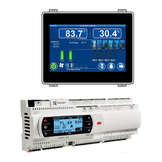
- Page 5 Figure 1 User Interface..........................8 Figure 2 Software information ........................20 Figure 3 Optional External display ......................21 Figure 4 System 2500 controller ......................... 21 Figure 5 power connection ......................... 22 Figure 6 Digital inputs ..........................23 Figure 7 Analog outputs ..........................25 Figure 8.
- Page 6 Figure 52 - Replacing windows cover......................55 Figure 53 - PCOWeb ............................ 60 Figure 54 - Window cover ........................... 60 Figure 55 - Installing PCOWeb ........................60 Figure 56 - Installing plastic cover ....................... 60 Compu-Aire Rev.01 03-27-17 Page 6 of 71...
-
Page 7: Introduction
The System 2500 is a programmable controller based on a double microprocessor, designed for precise "Smart" control of an air conditioning system. The System 2500 is made up of a microprocessor based MAIN BOARD equipped with a set of terminals used to interface the microcontroller board to the controlled devices such as compressors, fans, heaters, humidifiers, and valves. -
Page 8: Quick Reference Guide
Figure 1 User Interface Power/Link LED Solid green: Normal operation Flashing green: loss communication OFF: No power High contrast frame Touch sensitive screen Table 1 Touchscreen interface Compu-Aire Rev.01 03-27-17 Page 8 of 71... - Page 9 Active: Green Active: Red OFF: Black OFF: Black Demand output Pumpdown mode Evaporator fan Humidifier mode Dehumidification Cooling mode mode Econ/cooling assist Heating mode mode Table 2 Icon legends Compu-Aire Rev.01 03-27-17 Page 9 of 71...
- Page 10 Room temperature and relative humidity Room return temperature and humidity setpoints Cooling stages Mode of operation System ON/OFF control System demands/outputs Heating stages Navigation system Main menu Alarm menu Next menu Previous menu Table 3 Menu Options Compu-Aire Rev.01 03-27-17 Page 10 of 71...
-
Page 11: Sequence Of Operations
Unit will automatically control the necessary mode of operation to maintain room setpoints. 3.3 Lead/Lag Redundancy – pLAN Network System 2500 series controllers can be set for n+1 redundancy setup. A maximum of 32 units can be linked together on the pLAN network. The pLAN networked systems are identified by IP addresses. -
Page 12: Air Cooled Dx With Chilled Water Plus
DX cooling based on loss of water flow. When no water flow switch is selected for switch over, the unit will only work on either DX or C.W. cooling mode. Compu-Aire Rev.01 03-27-17 Page 12 of 71... - Page 13 If chilled water supply temperature is selected for switch over, than the unit shall continue with chilled water cooling if the chilled water supply temperature is below the required temperature setpoint and switch over to the DX cooling. Compu-Aire Rev.01 03-27-17 Page 13 of 71...
-
Page 14: Air Side Economizer
DX cooling coil. If the Water temperature drops below the Energy Miser setpoint, the condenser water is diverted to the free cooling coil and DX cooling will be programmed to either turned off or made available to assist based on demand. Compu-Aire Rev.01 03-27-17 Page 14 of 71... -
Page 15: Water Cooled Energy Miser
In the free cooling Energy Miser mode, the compressors will remain shut off while the fans of the unit shall be on. Humidification and Dehumidification modes shall operate as needed. 3.7 Water Cooled Energy Miser Summary of Equipment Compu-Aire Rev.01 03-27-17 Page 15 of 71... - Page 16 The Energy Miser mode depends on the entering water temperature and it is adjustable. Continuous water shall be flowing through the chilled water valve and will only supply Note: water to coil when called upon. Compu-Aire Rev.01 03-27-17 Page 16 of 71...
-
Page 17: Dry Fluid Cooler With Energy Miser
DFC is equipped with its own control panel that includes power block, fan contactors, aqua stats, freeze stats, relays and single or dual pump package control as necessary. Aqua stats are installed in the control panel and bulbs to be attached with leaving water header of the coil. Compu-Aire Rev.01 03-27-17 Page 17 of 71... - Page 18 The pump package shall include pump starters, aqua-stats, and fan cycling contactor(s) to control the condenser glycol temperature. The control panel shall be factory provided for filed installation in a weatherproof box provided on the Dry Fluid Cooler. The pumps Compu-Aire Rev.01 03-27-17 Page 18 of 71...
-
Page 19: Special Pump And Dry Fluid Cooler Control Logic
At 75 deg. F. exiting condenser water temperature fan speed is 100%. Controls shall monitor both fan KW and Pump KW energy consumption and determine best speed combination to maintain lowest condenser supply water temperature during DX cooling mode. Compu-Aire Rev.01 03-27-17 Page 19 of 71... -
Page 20: Optional Features
• Networking to a central command computer, or to an existing building automation system. The System 2500 is truly one of the most powerful and flexible controllers available for HVAC units today. CONFIGURATION The display unit is pre-configured at the factory for the most common user requirements. Some settings can be changed to adapt to the user’s specific needs. -
Page 21: Technical Specifications
(without requiring a backup battery). The controller also allows connection to the pLAN (Private Local Area Network) and can be connected to other System 2500 controllers. All the controllers in the pLAN can exchange information (variables, digital or analogue, depending on the application software used) at high transmission speed. -
Page 22: Mechanical Characteristics
The connection to the supervisor serial line, via the Modbus™, BACnet, or Lontalk protocols are also supported via RS485 standard or over TCP/IP connection. System 2500 is also equipped with USB peripheral that allowed easy firmware/software upgrade via a standard thumb drive. Each controller supports both LCD and touch screen interface. -
Page 23: Digital Inputs
Digital inputs are not optically isolated and have voltage free connects. Figure 6 Digital inputs Note: Separate the probe and digital input signal cables from the cables carrying the inductive loads and the power cables, to avoid possible Electromagnetic disturbance. Compu-Aire Rev.01 03-27-17 Page 23 of 71... -
Page 24: Universal Inputs
WARNING: The 21VDC available at the +Vdc terminal (J2) can be used to power any active probes, the maximum current is 150 mA, thermally protected against short-circuits. To supply the ratiometric 0 to 5V probes, use the +5VREF (max: 60 mA) present at terminal J24. Compu-Aire Rev.01 03-27-17 Page 24 of 71... -
Page 25: Analog Outputs
The 21VDC present at +Vterm (J24) can be used to power an external terminal with a maximum input of 2 W. Only one terminal can be connected (for example PLD terminal or ARIA terminal) in addition to the one connected to terminal J10. Compu-Aire Rev.01 03-27-17 Page 25 of 71... -
Page 26: Standard Input / Outputs
5.10 Standard Input / Outputs The following table defines standard I/O ports for the System 2500 controller. Refer to the electrical wiring diagram for actual wiring. Compu-Aire Rev.01 03-27-17 Page 26 of 71... -
Page 27: Optional Features
Multiple controllers may be used to combine cooling units into a pLAN network that operates as a single entity, enhancing the already-high performance and efficiency of units. System 2500 controllers are available as factory-installed assembly. Remote console box with graphic touch sensitive display wall-mount version is also available for remote operation and monitoring of cooling units. -
Page 28: Navigation Menu
• VNC server • HVAC • Trending • Network • Load system • Time & setup default Schedule • Password • About • Switch user • Techinican • Factory Figure 8. Menu tree Compu-Aire Rev.01 03-27-17 Page 28 of 71... -
Page 29: Figure 9. Alarm Status
Active alarm: View current active alarms. Alarm history: View previous stored alarms. Reset alarms: Reset all active alarms. Note alarm history is stored in flash and cannot be cleared. Figure 9. Alarm Status Compu-Aire Rev.01 03-27-17 Page 29 of 71... -
Page 30: Figure 10. Universal Inputs
Optional sensors show derived reading from connected sensors. The following calculated values are available. o Return/Outside air dew point o Return/Outside air enthalpy o 24 hours temperature min/max Figure 10. Universal inputs Figure 11. Universal outputs Compu-Aire Rev.01 03-27-17 Page 30 of 71... -
Page 31: Figure 12. Optional Sensors
Figure 12. Optional sensors Building Management System (BMS) The following protocols are supported by System 2500 via RS-485 (BMS2) and TCP/IP (Ethernet). Changes to protocol and baud rate requires system power cycle. Supporting protocol includes BACnet TCP/IP, BACnet MS/TP, Modbus, and LonTalk. -
Page 32: Figure 15. Trending Plot
Room humidity Discharge temperature Water in temperature Figure 15. Trending plot Trending history Start a real time trending Right scroll Left scroll Zoom in Zoom out Zoom full scale Legend on/off Compu-Aire Rev.01 03-27-17 Page 32 of 71... -
Page 33: Figure 16. Schedule
Use up/down arrow keys to update the values How to edit schedule: (Note: Schedule name is fixed and not editable) Tape on the desired schedule Tab on Enable check box to enable schedule Figure 16. Schedule Compu-Aire Rev.01 03-27-17 Page 33 of 71... -
Page 34: Figure 17. Sensor Calibration
Default offset for all the analog inputs are zero. To perform a calibration, enter the +/- values in the offset field. New changes take immediate effect. The value column shall show the immediate changes. Figure 17. Sensor calibration Compu-Aire Rev.01 03-27-17 Page 34 of 71... -
Page 35: Figure 18. Display Setup
Analog and digital outputs can be overridden at any given time. Each outputs can be as follows (changes are reflected under value column): Outputs Channel Option Analog outputs: AO[1:6] Auto, ON, OFF Digital outputs: DO[1:18] Auto, ON, OFF Figure 19. Manual controls Compu-Aire Rev.01 03-27-17 Page 35 of 71... -
Page 36: Figure 20. Network P-Lan Menu
Once the room setpoints are met, the standby units return to their offline stage. Figure 20. Network p-LAN menu Compu-Aire Rev.01 03-27-17 Page 36 of 71... -
Page 37: Figure 21. Ip Address
Date of month Rotation is based on selected day of the month such as every 1 of every month Num. of hours Rotation is based on number of active hours Figure 22. Rotation schedules Compu-Aire Rev.01 03-27-17 Page 37 of 71... -
Page 38: Figure 23. Network Configuration
Net Configuration By default, all System 2500 units are configured as standalone unit. To setup a network, a master and a minimum of one slave unit are required. The following modes are supported: Mode OFF, Slave, Master Master poll slave(s) heartbeat polling time... -
Page 39: Figure 25. Ip Configuration
Master unit is assigned a base IP address. All the slave units are assigned in the mapping table as shown in the Figure below: Figure 25. IP Configuration The Figure above shows the following settings are configured. Master IP 192.168.1.117 Slave1 IP 192.168.1.118 Slave2 IP 192.168.1.120 Compu-Aire Rev.01 03-27-17 Page 39 of 71... -
Page 40: Figure 26. Network Rotation Map
Network rotation map is configured by setting units as Active or Standby Force rotation is also achievable through this menu. Figure 26. Network rotation map The above image shows system 1 and system 3 are active. System 2 is set as standby. Compu-Aire Rev.01 03-27-17 Page 40 of 71... -
Page 41: Figure 27. Network Setup
Sensor failed alarm ON/OFF Heater OL Heater overload alarm ON/OFF Filter Dirty alarm ON/OFF Keyboard Off External keyboard (optional) ON/OFF Alarm Alarm function No action, next standby, all standby Figure 27. Network setup Compu-Aire Rev.01 03-27-17 Page 41 of 71... -
Page 42: Figure 28. Network Assist
The following network assist functions are supports. Once delay timeout, all standby units shall come online and perform assist function. Once setpoints are satisfied, previous standby systems shall go back in standby mode. Cooling Heating Humidity Dehumidification Figure 28. Network Assist Compu-Aire Rev.01 03-27-17 Page 42 of 71... -
Page 43: Factory Setup
Averaging temperature sensors Cond. Temp1 Condenser temperature 1 used in heatpump Cond. Temp2 Condenser temperature 2 used in heatpump User[1:3] User sensor1, sensor2, and sensor3 inputs Figure 29. Factory setting analog inputs Compu-Aire Rev.01 03-27-17 Page 43 of 71... -
Page 44: Analog Output
Condenser fan Condenser fan output. Requires HP transducer HG Reheat Hotgas reheat used in dehumidification Chilled water Chilled water output VFD comp Digital compressor output Figure 30. Factory Analog Outputs Compu-Aire Rev.01 03-27-17 Page 44 of 71... -
Page 45: Digital Inputs
C1/2 high pressure Pump al Pump failed alarm Remote On/OFF Fan overload Humidifier alarm Damper proof switch Compressor overload User1,2, 3 Figure 31. Digital Inputs Compu-Aire Rev.01 03-27-17 Page 45 of 71... -
Page 46: Digital Outputs
Unloader 2 Hot gas Bypass 1 Hot gas Bypass 2 Drain Selectable alarm Global alarm Humidifier Fan low speed Dehumidification Figure 32. Digital Outputs Compu-Aire Rev.01 03-27-17 Page 46 of 71... -
Page 47: Hvac
K proportional gain Interval time Derivative time Cycle Cycle time in second Figure 33. Evap PID tuning Figure 34. DX compressor PID tuning Figure 35. Heat PID tuning Figure 36. Humidity PID tuning Compu-Aire Rev.01 03-27-17 Page 47 of 71... -
Page 48: Loading System Default
Figure 41. Hotgas bypass PID tuning Figure 42. Condenser fan PID tuning 7.6 Loading System Default Loading system default returns system predetermined stage. Do not load default without consulting the factory as it wipes out all previous settings. Compu-Aire Rev.01 03-27-17 Page 48 of 71... -
Page 49: Password
Figure 44 Date and time 7.8.1 Night Setback The controller supports 7 days unoccupied and occupied modes. Separate temperature and humidity setpoints are available and take priority when the night setback mode is active. Compu-Aire Rev.01 03-27-17 Page 49 of 71... -
Page 50: Building Management System (Bms)
NIGHT SETBACK IS ONLY AVAILABLE ON THE TOUCH SCREEN USER INTERFACE. BUILDING MANAGEMENT SYSTEM (BMS) In addition to the built in BMS ports, The System 2500 is capable of communicating with external remote Building Management System (BMS) through the add on BMS Card interface. -
Page 51: Modbus
Pin-wiring of the connector is stamped on the card. If the card is placed in the last position of the supervision serial line, pins 2 and 3, you must connect a 120 Ω - 1/4 W end line resistors. Compu-Aire Rev.01 03-27-17 Page 51 of 71... - Page 52 • Absolutely avoid non-antistatic plastic bags, polystyrene or sponge. • Do not pass the card directly to other operators (to prevent from electrostatic induction and discharges). Compu-Aire Rev.01 03-27-17 Page 52 of 71...
-
Page 53: Lonworks
2. Terminal block for LonWorks® network (GND, A, 3. Service pin 4. Green service LED 5. Red fault LED Figure 48 - LONTalk Card Note: The ground wire (GND) is not requires in some application. Compu-Aire Rev.01 03-27-17 Page 53 of 71... -
Page 54: Led Color Description
• Absolutely avoid non-antistatic plastic bags, polystyrene or sponges. • Do not pass the electronic components or boards directly to other operators (to prevent electrostatic induction and discharges). Compu-Aire Rev.01 03-27-17 Page 54 of 71... -
Page 55: Connection To The Controller
To activate the service pin, simply momentarily short-circuit the two pins on the board (see Figure 24) with the tip of a screwdriver or a similar tool. The service pin must only be activated Compu-Aire Rev.01 03-27-17 Page 55 of 71... -
Page 56: Wink Event
In this specific case, the service LED on the interface comes on for one second, thus making it possible to check the correct operation of the connection between the interface and LonWorks® network. Compu-Aire Rev.01 03-27-17 Page 56 of 71... -
Page 57: Bacnet Over Tcp/Ip For Bms Card Add On
In order to access the configuration (see the Configuration section), the pCOWeb can be started using the “factory bootswitch parameters”: IP address= 172.16.0.1 Net mask= 255.255.0.0; “root” user password: froot “httpadmin” user password: fhttpadmin “guest” user password: fguest Compu-Aire Rev.01 03-27-17 Page 57 of 71... -
Page 58: Restarting The Software
Automatic network configuration (DHCP): ask the network administrator for the address that has automatically been assigned to the pCOWeb already connected; the administrator will need to know the MAC ADDRESS of the pCOWeb. Compu-Aire Rev.01 03-27-17 Page 58 of 71... - Page 59 To configure the DHCP function type “DHCP” in the place of the IP address. If the network does not use DHCP, ask the network administrator for a valid IP address and Netmask for the local network that the controller will be connected to. Compu-Aire Rev.01 03-27-17 Page 59 of 71...
-
Page 60: Web Server
The system can be accessed via a telnet terminal or via FTP. Authentication with user name and password is required for each access. The following users are registered. User Name Description Default Password Allowed root administrator of the operating froot no limitation system Compu-Aire Rev.01 03-27-17 Page 60 of 71... -
Page 61: Cgi Script
The parameters relating to the management of the SNMP protocol can be set using the administrator configuration pages. 8.3.10 BACNET PCOWeb is able to communicate using the BACnet protocol over Ethernet: • ISO8802-2 over 8802-3; • BACnet/IP. Compu-Aire Rev.01 03-27-17 Page 61 of 71... -
Page 62: Warnings
• Always avoid using plastic, polystyrene or non-antistatic materials; • Always avoid passing the board between operators (to avoid the phenomena of electrostatic induction and consequent discharges). Compu-Aire Rev.01 03-27-17 Page 62 of 71... -
Page 63: Banet Over Ms/Tp For Bms Card Add On
2kV, connector G0 on the controller must be grounded. The board cannot be installed in direct contact with the metal panel on the electrical panel. Status RS-485 Push Button Table 6- Installation guide Compu-Aire Rev.01 03-27-17 Page 63 of 71... -
Page 64: Meaning Of The Jumpers
Quick green-OFF-green if communication with the controller is OK (pCO* ON-LINE); • Slow red-OFF-red if communication has not been established with the pCO* (controller OFF-LINE) • Green-red-green if PCOnet detects errors or a temporary lack of response from the controller. Compu-Aire Rev.01 03-27-17 Page 64 of 71... - Page 65 5 seconds and no more than 10 seconds. Approximately 10 seconds after releasing the button, the Status LED will stop flashing, and 15 seconds later PCOnet will be restarted: Status LED quickly flashing red-green-red-green. Compu-Aire Rev.01 03-27-17 Page 65 of 71...
-
Page 66: Recalling The Factory Configuration ("Factory Bootswitch" Mode)
Note: If the values of the PCOnet parameters are not suitable, communication with BACnet may not be possible. To connect to PCOnet, restart PCOnet using “factory bootswitch” mode (see the section on Operation - Pushbutton). Compu-Aire Rev.01 03-27-17 Page 66 of 71... -
Page 67: Bacnet Parameter Description
This baud rate is not supported by the RS232 serial port on a normal PC. Parameter Factory Device Instance 4194303 77000 Station Address Max Master Max Info Frames Baud Rate 9600, 19200, 38400,76800 Table 7 - BACnet MS/TP parameters Compu-Aire Rev.01 03-27-17 Page 67 of 71... -
Page 68: Troubleshooting Guide
Cabling Verify the physical wires between the controller and the BMS system. A parallel cable should be in used. Not commission Decommission and commission the card. Use a Wink command to check response. Compu-Aire Rev.01 03-27-17 Page 68 of 71... - Page 69 Incorrect setpoint Check system setpoint for cooling temperature. Compressor only runs when temperature drops below room setpoint. Reheat Lockout Over amp protection System incorporate a reheat lockout if cooling and humidifier are ON Compu-Aire Rev.01 03-27-17 Page 69 of 71...
- Page 70 Max ON if needed. Heater Overheat Heater overload Check if heater is overloading. Check and reset alarm after rectifying the problem Incorrect trigger level Verify setting under “Technician->DI Setup->Heater Overheat” Alarm IF=Closed Compu-Aire Rev.01 03-27-17 Page 70 of 71...
- Page 71 TECHNICAL SUPPORTS www.compu-aire.com Tel: (562) 945-8971 Fax: (562) 696-0724 UNITED STATES OFFICE Compu-Aire, Inc. 8167 Byron Rd. Whittier, CA 90606 SUBJECT TO CHANGE WITHOUT INCURRING OBLIGATION Compu-Aire Rev.01 03-27-17 Page 71 of 71...
Need help?
Do you have a question about the SYSTEM 2500 and is the answer not in the manual?
Questions and answers