
Related Manuals for Harris Ranger Series


Summary of Contents for Harris Ranger Series
- Page 1 TECHNICAL MANUAL 888-2685-001 Ranger Series™ Commissioning Manual Ranger Series™ Commissioning Manual Rev. A1, Dec. 24, 2007 T.M. No. 888-2685-001 PRELIMINARY © Copyright Harris Corporation 2007 All rights reserved...
- Page 2 HARRIS Service Parts Department. Telephone 217/222-8200 to contact the service parts department or address correspondence to Service Parts Department, HARRIS CORPORATION, Broadcast Systems Division, P.O. Box 4290, Quincy, Illinois 62305-4290, USA. The HARRIS factory may also be contacted through a FAX facility (217/221-7096). NOTE: The # symbol used in the parts list means used with (e.g.
- Page 3 Manual Revision History Ranger ™ Mobile Commissioning Manual REV. DATE Pages Affected Rev A 9/20/07 Prelim. Created and Manual Sent To Review Rev A1 12/24/07 Prelim. Added exciter settings. 12/24/07 888-2685-001 MRH-1 WARNING: Disconnect primary power prior to servicing.
- Page 4 888-2685-001 12/24/07 MRH-2 WARNING: Disconnect primary power prior to servicing.
- Page 5 12/24/07 888-2685-001 WARNING: Disconnect primary power prior to servicing.
- Page 6 • In the ten digit part numbers, if the last three numbers are 000, the item is a part that Harris has purchased and has not manufactured or modified. If the last three numbers are other than 000, the item is either manufactured by Harris or is purchased from a vendor and modified for use in the Harris product.
- Page 8 HARRIS CORPORATION shall not be responsible for injury or damage resulting from improper procedures or from the use of improperly trained or inexperienced personnel performing such tasks.
- Page 9 12/24/07 888-2685-001 WARNING: Disconnect primary power prior to servicing.
- Page 10 FIRST-AID Personnel engaged in the installation, operation, maintenance or servicing of this equipment are urged to become familiar with first-aid theory and practices. The following information is not intended to be complete first-aid procedures, it is a brief and is only to be used as a reference.
- Page 12 888-2685-001 12/24/07 WARNING: Disconnect primary power prior to servicing.
-
Page 13: Table Of Contents
Table of Contents Section 1 Remote Status Outputs, J15 & J16 ... .2-28 Remote Power Metering, J17 ....2-30 Introduction Purpose of This Manual . - Page 14 Table of Contents (continued) Report Cover Page ..... . . 4-1 Spurious Emissions Test Results ..4-27 Table of Contents .
- Page 15 Table of Contents (continued) Control System ISP Procedure ....6-3 PA Module ISP Procedure ....6-8 ISP Errors .
- Page 16 Table of Contents (continued) 888-2685-001 12/24/07 WARNING: Disconnect primary power prior to servicing.
-
Page 17: Purpose Of This Manual
Ranger Commissioning Manual Section 1 Introduction Purpose of This Manual This technical manual contains the information pertaining to the commissioning of the Ranger™ Series, solid-state, UHF transmitter, with APEX exciter, featuring FLO Technology. The various sections of this technical manual provide the following types of information. •... -
Page 18: Ranger Transmitter Models
Ranger Commissioning Manual Section 1 Introduction Ranger Transmitter Models The Ranger Series™ transmitter utilizing FLO technology is available in 2 power levels as listed in Table 1-1.Both systems are designed to use external (low loss) mask filters for maximum usable RF power output. -
Page 19: System Block Diagrams
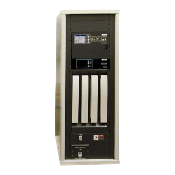
Ranger Commissioning Manual Section 1 Introduction Figure 1-1 Ranger Transmitter - Front View System Block Diagrams Figure 1-2 shows the system block diagram of the CZ1000F Ranger Transmitter. The CZ500F model has only 1 PA Module and is identical to the CZ1000F with the following items deleted: •... - Page 20 Ranger Commissioning Manual Section 1 Introduction Figure 1-2 Ranger Series™ System Block Diagram 888-2685-001 12/24/07 WARNING: Disconnect primary power prior to servicing.
-
Page 21: Transmitter Control System
Ranger Commissioning Manual Section 1 Introduction Transmitter Control System The transmitter uses a distributed architecture control system. This means that each transmitter sub-system is responsible for its own monitoring and protection and simply reports back to the Main Controller for display on the GUI (Graphical User Interface) or to a remote interface. The heart of the system is the 376 Micro Module which is used in all of the transmitter systems for control, monitoring and protection. -
Page 22: In-System Programming Or Isp
CD-ROM accompanying this manual along with all of the transmitter software as it shipped from the factory. The Harris ISP program is easy to use and it only takes a few minutes to load or update software. - Page 23 Ranger Commissioning Manual Section 1 Introduction SWITCHED SS RELAY +32V +32V ON/OFF PHASE RF IN & GAIN BIAS TEMP SHORT LDMOS FAULT CONTROL BOARD TO MAIN CONTROLLER MODULE ENABLE Figure 1-3 PA Module Block Diagram Each PA module consists of the following components: a.
-
Page 24: Power Supplies
Ranger Commissioning Manual Section 1 Introduction Each Ranger Series™ PA Module is a self-contained transmitter (except for the power supply) with its own internal control, monitoring and protection. The modules only receive basic On/Off, Mute, Restart, Phase and Gain commands from the transmitter control system. This means that each module will protect itself without relying on the system controller. - Page 25 Ranger Commissioning Manual Section 1 Introduction Unit Item Conditions Value Data Input Input Rate Mb/s Impedance Ohms DVB- Standard EN 50083-9 Connector BNC Female External Frequency Reference Input Frequency 10 Mhz Impedance Ohms 50 Ohms Level Sinusoidal Waveform 0 to +10 dBm Connector BNC Female Performance...
- Page 26 Ranger Commissioning Manual Section 1 Introduction Unit Item Conditions Value AC Line Voltage Single Phase 50/60 Hz 208/240 VAC AC Line Voltage Variation +/-10% Power Factor > 0.97 20% (for CZ500F & Overall Efficiency (Typical) AC power to RF average power CZ1000F) Power Consumption 2.5kW for CZ500F...
-
Page 27: Introduction
Ranger Commissioning Manual Section 2 Installation Verification & Initial Turn-on Introduction This section includes the information necessary for installation confirmation prior to initial system start-up of the Ranger™ Series, solid state UHF transmitter. Information is included for single and dual PA module configurations. Due to the modular nature of the Ranger, all models have similar installation and testing procedures. - Page 28 Ranger Commissioning Manual Section 2 Installation Verification & A - ASI and optional 10MHz reference inputs for the exciter B - Total Forward and Reflected power samples (after filter) and RTAC sample for the exciter C -Low Voltage Power Supply switch and fuse assembly D - Exciter Interface Board E - External I/O Board.
- Page 29 Section 2 Installation Verification & Ranger Commissioning Manual A - Control panel with GUI Touchscreen B - Apex Exciter C - PA Module #1 D - PA Module #2 for CZ1000F (blank panel in CZ500F) E - Blank panels F - Control Circuit Breaker, CB1. Supplies power for the LV PSU (J).
-
Page 30: Documentation
Ranger Commissioning Manual Section 2 Installation Verification & Documentation The following is a list of documentation that ships with the transmitter. This documentation should be available for reference during the commissioning process. The top level Document Package numbers for each transmitter model are shown below: •... -
Page 31: Installation Confirmation Checkboxes
Section 2 Installation Verification & Ranger Commissioning Manual d. RF Flow Diagram - 843-5560-097 - Shows external RF connections and possible layout for patch panel and dummy load. e. Ranger External I/O Connections - 843-5560-105 - Shows connections to the External I/O board for an RF patch panel or motorized switch. - Page 32 Ranger Commissioning Manual Section 2 Installation Verification & input must be equipped with automatic voltage regulators (optional equipment) capable of correcting the mains voltage. The Primary AC conduit is securely attached to the top of the transmitter cabinet. The top of the transmitter cabinet has a pre-cut hole for a 3/4” conduit connection. For Conduit connections to the transmitter refer to the Transmitter Outline Drawing 843- 5560-071, Top View.
-
Page 33: Signal And Ground Connections
Section 2 Installation Verification & Ranger Commissioning Manual Signal and Ground Connections NOTE: Control and signal wires should never be run in the same conduit with any AC wiring. A separate conduit should be used for control/signal cables. Confirm that the ASI input is connected to the terminal (may be labeled SMPTE 310M as seen in the photo). -
Page 34: External Interlocks
Ranger Commissioning Manual Section 2 Installation Verification & 2.7.1 External Interlocks The transmitter has inputs for up to four External Interlock jumpers installed on-site. external interlocks on the External I/O To detector Board. Note that these 4 connections Customer Interlock #1 Circuit comprise one interlock with 4 series Ext. -
Page 35: Port Patch Panel Connection Confirmation
Section 2 Installation Verification & Ranger Commissioning Manual 3 Port Patch Panel Connection Confirmation IMPORTANT: If no patch panel or motorized switch is to be installed in the transmitter RF out- put line, or if the patch panel does not have status switches, then a jumper must be placed on the External I/O board from J14-3 (RF_SW_A_STAT) to J14-1 (ground). -
Page 36: Motorized Rf Switch Connections (If Equipped)
Ranger Commissioning Manual Section 2 Installation Verification & Motorized RF Switch Connections (if equipped) IMPORTANT: If no patch panel or motorized RF switch is to be installed in the transmitter RF output line, or if the RF switch does not have status switches, then a jumper must be placed on the External I/O board from J14-3 (RF_SW_A_STAT) to J14-1 (ground). -
Page 37: Pa And Ps Module Installation
PERATURE. DO NOT TOUCH THE MODULES WITH BARE HANDS AFTER THE TRANSMITTER HAS BEEN RUNNING, ESPECIALLY IN HIGH AMBIENT TEMPERA- TURE ENVIRONMENTS. SPECIAL GLOVES HAVE BEEN PROVIDED IN THE REAR OF THE CABINET OR CAN BE OBTAINED FROM HARRIS, PART #0990006483 OR GRAINGER ITEM #4JF36. 12/24/07... -
Page 38: Initial Turn-On
Ranger Commissioning Manual Section 2 Installation Verification & 2.11 Initial Turn-On Read and understand the entire initial turn-on procedure before starting. Detailed use of all GUI screens is given in Section 3 Operation/Alignments. Shut off the control circuit breaker CB1 and the PS Module breaker (both located on the bottom front of the transmitter). - Page 39 Section 2 Installation Verification & Ranger Commissioning Manual PA PS: Reading will be zero at Any Power Supply this time. faults would cause this icon to turn red Figure 2-5 Power Supply Metering NOTE: The PAPS (Power Amplifier Power Supply) readings should be zero and will be shown as OFF.
- Page 40 Ranger Commissioning Manual Section 2 Installation Verification & This adjustment will only need to be done during installation or in the event the MOV board or the PS Monitor board is changed. Figure 2-6 PS Service Screen Customize the transmitter System Setup. Press the SYSTEM button then enter the default password - 1895.
-
Page 41: Exciter Setup
Section 2 Installation Verification & Ranger Commissioning Manual Press the CONTROL SETUP button in Figure 2-7 to set the Date, Time, LCD screen contrast and Password on the Control Setup screen, shown in Figure 2-8. Touch the screen at each field to enter the correct data for Date, time, contrast and password. -
Page 42: Verify Exciter Signal Connections
Ranger Commissioning Manual Section 2 Installation Verification & 2.11.1.1 Verify Exciter Signal Connections Most of the input and output connections are at the rear of the exciter, only the RS232 connections are available at the front and rear. Figure 2-9 shows the rear panel connections. -
Page 43: Ac Power
Section 2 Installation Verification & Ranger Commissioning Manual PA SAMPLE IN (SMA) should have a cable connected to it that comes from the output of the transmitter power amplifier, taken before the HPF and after the PA combiner for transmitters with multiple PAs. It is used by RTAC™ to correct for the nonlinear distortion caused by the power amplifier. -
Page 44: Verify Exciter Configuration
Ranger Commissioning Manual Section 2 Installation Verification & Figure 2-10 on page 2-18 shows two methods of distributing the 1PPS signal. Apex GPS 1PPS Exciter Source For a single 1PPS run from source to exciter, set the exciter FPGA modulator board 1PPS input termination jumper (JP1) to position 1 - 2 (50 ohm termination). -
Page 45: Verify Configuration Of Setup Screens
Section 2 Installation Verification & Ranger Commissioning Manual 2.11.1.4.1 Verify Configuration of Setup Screens NOTE: The screen menus are given in Italics before the setup values. Main Screen. Set exciter RF output power (the display reads average power) Normal value is less than 120 mW. -
Page 46: Verify Configuration Of Fpga Screens
Ranger Commissioning Manual Section 2 Installation Verification & Change passwords as required to satisfy operational requirements. Main Screen > Setup > User Setup (Lock or Unlock). Lock or unlock User Setup to satisfy operational requirements. Main Screen > Setup > Diagnostic Setup (Lock or Unlock). Lock or unlock Diagnostic Setup to satisfy operational requirements. -
Page 47: Verify Configuration Of Status Screens
Section 2 Installation Verification & Ranger Commissioning Manual • LID: Unsigned Decimal, range 0-15. XXX Define • Superframe Length - Display Only • Frame Length - Display Only • Local Length - Display Only. 2.11.1.6 Verify Configuration of Status Screens When configuring an exciter for the first time, it is useful to check certain portions of the following status screens. -
Page 48: Normal Settings For Diagnostic Screens
Ranger Commissioning Manual Section 2 Installation Verification & 2.11.1.7 Normal Settings for Diagnostic Screens The Diagnostics screens offer tests used to diagnose exciter problems. If the diagnostic selections are left in the wrong states, normal operation of the exciter could be impaired. -
Page 49: Rf Initial Turn On
Section 2 Installation Verification & Ranger Commissioning Manual 2.11.2 RF Initial Turn ON Shut the transmitter OFF. The transmitter should be initially powered into a test load. Measure the test load impedance prior to application of RF power. The load can be measured with a network analyzer prior to application of RF. - Page 50 Ranger Commissioning Manual Section 2 Installation Verification & Check the power on the HOME screen (shown in Figure 2-4) to check for excessive reflected power after the mask filter. All PAs should show a green (OK) status on the GUI (Power Amp screen). Monitor the PA Meters screen shown in Figure 2-13.
- Page 51 Section 2 Installation Verification & Ranger Commissioning Manual NOTE: This adjustment should only be done at full power and after the module tempera- tures have had time to stabilize. PA Module phasing should always be optimized after finishing this procedure. Press the RESET button.
-
Page 52: Parallel Remote Control Connections
Ranger Commissioning Manual Section 2 Installation Verification & Press transmitter off button to turn off RF output power. Measure the antenna and transmission line impedance prior to application of RF power to the antenna system. The transmission line and antenna can be measured with a network analyzer prior to application of RF. -
Page 53: Transmitter Control Functions, J13 And J14
Section 2 Installation Verification & Ranger Commissioning Manual * Not Used NOTE: EXTERNAL I/O BOARD REMOTE CONNECTOR Left half of PC LOCATIONS AND PINOUTS Board not shown NOT USED FOR RANGER Figure 2-15 External I/O Connector Locator 2.12.1 Transmitter Control Functions, J13 and J14 All control inputs use opto-isolators for surge protection. -
Page 54: Section 1 Remote Status Outputs, J15 & J16
Ranger Commissioning Manual Section 2 Installation Verification & Table 2-1 J13 & J14, External I/O Board, Remote Control Connectors Connector Schematic Function Label J13-5 /INPUT 4 REMOTE LOWER J13-6 Ground J13-7 Ground J13-8 /INPUT 5 Spare J13-9 /INPUT 6 Spare‘ J13-10 /INPUT 7 REMOTE_RF MUTE_ON- Transmitter RF output is muted as long as this input... - Page 55 Section 2 Installation Verification & Ranger Commissioning Manual indications can be supplied via J15 & J16 or can be supplied by an external voltage source. The status output connections are listed in Table 2-2. Table 2-2 J15 & J16, External I/O Board, Remote Status Outputs Connector Schematic Label Status Output...
-
Page 56: Remote Power Metering, J17
Ranger Commissioning Manual Section 2 Installation Verification & 2.13.1 Remote Power Metering, J17 Each analog metering output will provide 0 - 4.096Vdc output into a 400 ohm load (where 3Vdc = Nominal). The connections for J17 are listed in Table 2-3. Table 2-3 J17, External I/O Board, Remote Power Metering Connection... -
Page 57: Operation And Adjustments
Ranger Commissioning Manual Section 3 Operation and Adjustments Introduction This section gives detailed operation and adjustment information for the Ranger™ Series Solid-State UHF Series transmitter. It contains all information necessary to make any operational changes or adjustments which appears on any of the Graphical User interface (GUI) Touchscreen display screens. -
Page 58: Main Menu "Hardware" Buttons
Section 3 Operation and Adjustments Ranger Commissioning Manual 3.2.1 Main Menu “Hardware” Buttons Just to the right of the touchscreen, there are 5 hardware buttons which are part of the front panel overlay. Located next to each button is a Status LED which illuminates green under normal, no fault conditions. -
Page 59: Global Status And Navigation
Section 3 Operation and Adjustments Ranger Commissioning Manual 3.3.1 Global Status and Navigation The top 2 lines of the touchscreen display (shown in Figure 3-2) are considered global because they show up on all screens. The top line gives the transmitter model number and the station name and/or location which is entered by the customer in the System Setup screen, in Figure 3-22, with a maximum of 24 characters including spaces. -
Page 60: Gui Home Page
Section 3 Operation and Adjustments Ranger Commissioning Manual GUI Home Page The HOME screen shown in Figure 3-3 is the primary operator screen and the default screen after boot up. The HOME screen contains the most important general operator information such as: a. -
Page 61: Drive Chain Main Menu
Section 3 Operation and Adjustments Ranger Commissioning Manual NOTE: To simplify the discussion of GUI navigation, the following will navigate and describe all of the screens under each of the 5 main menu buttons located to the right of the touchscreen display (and on the right side of the GUI Home screen). Drive Chain Main Menu If you press the Drive Chain button on the control panel overlay, or the Drive Chain button on the HOME screen,... -
Page 62: Drive Service
Section 3 Operation and Adjustments Ranger Commissioning Manual 3.5.1 Drive Service When the “Drive Service” button in Figure 3-4 is pressed, it will bring up the screen shown in Figure 3-5. This screen allows for calibration of the exciter power reading on the Drive Chain screen in Figure 3-4. -
Page 63: Power Amp Main Menu
Section 3 Operation and Adjustments Ranger Commissioning Manual Power Amp Main Menu If you press the Power Amp button on the control panel overlay, or the Power Amp button on the HOME screen, it will take you to the screen shown in Figure 3-6. The Power Amp Menu Tree is shown in Figure 3-32 on page 3-33. -
Page 64: Pa Faults
Section 3 Operation and Adjustments Ranger Commissioning Manual 3.6.1 PA Faults This screen is basically a list of all of the faults monitored in each PA Module. • An active fault will be highlighted in RED • A warning condition will be highlighted in YELLOW. The PA Faults screen in Figure 3-7, shows that PA Module #2 has 1 LDMOS fault and a Frequency warning. - Page 65 Section 3 Operation and Adjustments Ranger Commissioning Manual Table 3-1 PA Module Faults Fault Fault limit Action Taken Frequency Channel frequency or frequency band reported by module does Warning not match system settings. Affects Module Calibration. EEPROM Error was detected writing to EEPROM on Module Controller Warning Reference +5V reference voltage is not within tolerance...
-
Page 66: Pa Meters
Section 3 Operation and Adjustments Ranger Commissioning Manual 3.6.2 PA Meters This screen is accessed by pressing the “PA Meters” button in Figure 3-6 or Figure 3-7. A complete set of PA Meter readings is given in the Factory Test Data. The Factory Test Data readings are taken at rated power unless otherwise specified by the customer. -
Page 67: Pa Data
Section 3 Operation and Adjustments Ranger Commissioning Manual 3.6.3 PA Data The PA Data screen in Figure 3-9 is accessed from the PA Meters screen in Figure 3-8. It contains vital information about the operation of the PA module. The readings are ADC or DAC counts in either 10 bit (0 - 1023) or 12 bit (0 - 4095). - Page 68 Section 3 Operation and Adjustments Ranger Commissioning Manual d. DAC Counts - These are 10 bit (0-1023) ADC samples of the detected RF input and Forward and Reflected power output. • IN - Is a sample of the detected RF drive input to the module. Nominal input for 400W output is 15mW.
-
Page 69: Pa Service
AFTER THE TRANSMITTER HAS BEEN RUNNING, ESPECIALLY IN HIGH AMBIENT TEMPERATURE ENVIRONMENTS. SPECIAL GLOVES HAVE BEEN PROVIDED IN THE REAR OF THE CABINET OR CAN BE OBTAINED FROM HARRIS, PART #0990006483 OR GRAINGER ITEM #4JF36. To Figure 3-11 To Figure 3-6... -
Page 70: Pa Setup (Gain Balance)
Section 3 Operation and Adjustments Ranger Commissioning Manual 3.6.4.1 PA Setup (Gain Balance) This screen is accessed by pressing the PA Setup button in Figure 3-10. Its sole purpose is to balance the gain of the 2 PA modules in the CZ1000F transmitter. The goal is to match the 2 module gain readings. -
Page 71: Output Main Menu
Section 3 Operation and Adjustments Ranger Commissioning Manual Output Main Menu If you press the Output button on the control panel overlay, or the Output button on the HOME screen, it will take you to the screen shown in Figure 3-12. The Output Menu Tree is shown in Figure 3-31 on page 3-33. - Page 72 Section 3 Operation and Adjustments Ranger Commissioning Manual b. Output Power Meters - This panel gives the Forward and reflected power outputs both before and after the built-in mask filter. c. Output Control - This area of the screen can be used to control an external motor- ized RF switch so that the transmitter can be switched from Antenna to the Test Load, provided the System Configuration screen in Figure 3-23 on page 3-28 is set for “Motor”.
-
Page 73: Output Service
Section 3 Operation and Adjustments Ranger Commissioning Manual 3.7.1 Output Service This screen is accessed from the Output screen in Figure 3-12. It is used for 2 purposes: a. To monitor the PA Module Circulator reject power. Provides a bargraph and a DAC count of 0 - 1023 (0 meaning no reflected power and 1023 being maxi- mum). -
Page 74: Module Phasing Procedure
Section 3 Operation and Adjustments Ranger Commissioning Manual 3.7.2 Module Phasing Procedure NOTE: This procedure is for the CZ1000F only. The goal is to minimize the PA module combiner reject load power reading in Figure 3- 13, by adjusting the phase of module #2. The phase of PA module #1 is fixed. The “PA 1&2”... -
Page 75: Output Setup
Section 3 Operation and Adjustments Ranger Commissioning Manual 3.7.2.1 Output Setup This screen is accessed by pressing the Output Setup button on the Output Service screen in Figure 3-13. It is used to calibrate the filter input power and Total cabinet Forward and Reflected power (after the filter). -
Page 76: Forward And Reflected Power Calibrations
Section 3 Operation and Adjustments Ranger Commissioning Manual 3.7.3 Forward and Reflected Power Calibrations The following procedure is used to calibrate the forward and reflected power readings via the Output Setup screen. The forward must be calibrated first, then the reflected can be calibrated. -
Page 77: Power Supply Main Menu
Section 3 Operation and Adjustments Ranger Commissioning Manual Power Supply Main Menu If you press the Power Supply button on the control panel overlay, it will take you to the screen shown in Figure 3- 16. The Power Supply Menu Tree is shown in Figure 3-32 on page 3-33. -
Page 78: Ps Service
Section 3 Operation and Adjustments Ranger Commissioning Manual 3.8.1 PS Service This is an on-line help screen telling how to remove a power supply, but also allows for calibration of the AC Mains reading on the Power supply screen in Figure 3-16. CAUTION: ALWAYS SHUT THE BREAKER OFF ON THE FRONT OF THE PA POWER SUPPLY BEFORE REMOVING TO PREVENT DAMAGE TO CONTACTS AND/... -
Page 79: System Main Menu
Section 3 Operation and Adjustments Ranger Commissioning Manual System Main Menu If you press the System button on the control panel overlay, it will take you to the screen shown in Figure 3- SYSTEM 18. The System Menu Tree is shown in Figure 3-33 on page 3-34. -
Page 80: Control System
Section 3 Operation and Adjustments Ranger Commissioning Manual 3.9.1 Control System The Control system screen in Figure 3-19 is a status and fault screen for the parallel control bus lines and the internal serial communication bus to each of the controller boards and the PA Module(s). -
Page 81: System Log
Section 3 Operation and Adjustments Ranger Commissioning Manual 3.9.2 System Log This screen is accessed by pressing the System Log button on the System screen in Figure 3-18. It is a complete listing of all transmitter and system faults in the order in which they occurred. -
Page 82: System Service
Section 3 Operation and Adjustments Ranger Commissioning Manual 3.9.3 System Service This screen is accessed by pressing the System Service button in Figure 3-18. This screen simply provides information concerning the use of the sub-menus accessed from this point. These are: a. -
Page 83: System Setup
Section 3 Operation and Adjustments Ranger Commissioning Manual 3.9.3.1 System Setup This screen provides a way to change important pieces of information which are then used throughout the GUI. To make a change, simply touch the white text box and a pop- up window will allow you to enter the new information. -
Page 84: System Configuration
Section 3 Operation and Adjustments Ranger Commissioning Manual 3.9.3.1.1 System Configuration This screen is used to configure the transmitter to operate with either a 3 port patch panel or a motorized RF switch. To change this setting touch the white text box and the Output Switch pop up widow will appear (as shown in Figure 3-23). -
Page 85: Touch Screen Calibration
Section 3 Operation and Adjustments Ranger Commissioning Manual in which information can be changed. The default password is 1895, which will override any other password and allow access. The only function button is the Touch Cal or Touchscreen Calibration. This should not require routine adjustment. - Page 86 Section 3 Operation and Adjustments Ranger Commissioning Manual To test the calibration simply touch the screen in several places to make STEP 3 sure an X shows up where you touched. If the calibration is good, then press ACCEPT. If not, press CANCEL STEP 4 and the cal procedure will be started over.
-
Page 87: Software Revisions (Sw Revs)
Section 3 Operation and Adjustments Ranger Commissioning Manual 3.9.3.2 Software Revisions (SW REVs) This screen shows the software revision for all transmitter controllers and PA module controllers. This information should be known before calling for technical support. To Figure 3-28 To Figure 3-21 Figure 3-27 Software Revisions Screen 3.9.3.2.1 Hardware Revisions... -
Page 88: Gui Menu Structures
Section 3 Operation and Adjustments Ranger Commissioning Manual 3.10 GUI Menu Structures The following figures are simply showing all of the possible screens which can be accessed on the GUI. This is mainly helpful when learning to navigate. The shaded block at the top of each menu tree represents the Main Menu which is accessed using the Quick navigation hardware button on the Control Panel or one of the 5 software buttons on the right side of the HOME Page. - Page 89 Section 3 Operation and Adjustments Ranger Commissioning Manual OUTPUT Main Menu Output Service Output Setup Figure 3-31 Output Menu Structure POWER SUPPLY Main Menu Service Figure 3-32 Power Supply Menu Structure 12/24/07 888-2685-001 3-33 WARNING: Disconnect primary power prior to servicing.
- Page 90 Section 3 Operation and Adjustments Ranger Commissioning Manual SYSTEM Main Menu Control System System System Service System Software Setup Revision Hardware Output Configuration Control Revision Setup (output Switch ) Setup Touch Screen Calibration Figure 3-33 System Menu Structure 3-34 888-2685-001 12/24/07 WARNING: Disconnect primary power prior to servicing.
-
Page 91: Rf Testing
Ranger Commissioning Manual Section 4 RF Testing Introduction This section defines suggested data and measurements that are to be included in the report that should be generated as part of a Ranger Transmitter Proof of Performance. The various sections of the report and measurements are defined and in some instances samples are provided. -
Page 92: Table Of Contents
Section 4 RF Testing Ranger Commissioning Manual 4.2.2 Table of Contents Table 4-1 describes the content of a typical Performance Report. The page numbers are added as the report is generated. The report contents may also need to be modified depending on specific site requirements or equipment provided. -
Page 93: Facilities Authorized In Construction Permit
Section 4 RF Testing Ranger Commissioning Manual 4.2.3 Facilities Authorized in Construction Permit • Name of Applicant: • Call Letters: • Channel Number: • File Number of License: 4.2.4 Transmitter Location • State: • County • City: • Street Address: 4.2.5 Transmitter Manufacturer ID Plate Insert photograph of transmitter identification plate in this section. -
Page 94: Rf Power Summary
Section 4 RF Testing Ranger Commissioning Manual 4.2.6 RF Power Summary Table 4-2 RF Power Budget (Average, Digital) Description Watts Amplifier(s) Rated Power Transmitter System Rated Power Transmitter Power Output (TPO) Transmission Line Loss Antenna Input Power Antenna Power Gain (Maximum) Effective Radiated Power (Average) TPO (dBK) - Transmission Line Loss (dB) + Antenna Gain (dB) = ERP (dBK) 10 x Log TPO(kW) = dBK... -
Page 95: System Block Diagram
Section 4 RF Testing Ranger Commissioning Manual 4.2.8 System Block Diagram A simplified block diagram should be included in the report. A sample diagram is shown below. The diagram should define signal flow and major components in the system under test. The diagram may vary from site to site depending on the specific site layout and equipment. -
Page 96: Test Equipment List
Section 4 RF Testing Ranger Commissioning Manual 4.2.9 Test Equipment List Table 4-3 Test Equipment for Measurements Test Equipment Mfg. Model Serial No. Spectrum Analyzer R&S FSQ3 Network Analyzer HP8714B RF Power Meter E4418A Power Sensor 8482H Frequency Counter HP53181A Qualcomm MER Tool Set NOTE: The test equipment outlined above is an example of typical equipment used to... -
Page 97: Requirement(S)
Section 4 RF Testing Ranger Commissioning Manual 4.2.10.2 Requirement(s) The output power shall be measured using a true RMS RF power meter and a precision directional coupler. Output power shall be 375 or 750 W (within +/- 10%) 4.2.10.3 Setup and Test Equipment Table 4-4 Power Measurement Setup Transmitter... -
Page 98: Power Measurement Procedure
Section 4 RF Testing Ranger Commissioning Manual 4.2.10.4 Power Measurement Procedure Step Procedure Description Expected Observation Configure the transmitter to operate on air with Exciter A with precorrector settings to: Non-Linear Precorrection = ADAPT Linear Precorrection = BYPASS Connect the true RMS power meter Measured power output is probe to the transmitter output within +/- 10% of rated... -
Page 99: Frequency Tolerance
Section 4 RF Testing Ranger Commissioning Manual 4.2.11 Frequency Tolerance 4.2.11.1 Objective To verify the Channel Center Frequency meets the tolerance requirements. The transmitter will be operated in CW mode (719 MHz for U.S. applications and at other frequencies to be defined by Qualcomm for international operation) while the frequency is measured at the transmitter forward output directional coupler. -
Page 100: Frequency Tolerance Procedure
Section 4 RF Testing Ranger Commissioning Manual 4.2.11.4 Frequency Tolerance Procedure Step Procedure Description Expected Observation Generate a CW tone as per the instructions in Appendix B. Using a frequency counter (or a The maximum deviation of the car- spectrum analyzer) measure the fre- rier tone from 719000000 should be quency of the tone coming out of the less than ±1.0 Hz... -
Page 101: Non-Linear Precorrection
Section 4 RF Testing Ranger Commissioning Manual 4.2.12 Non-Linear Precorrection (Shoulders & Amplitude Response) 4.2.12.1 Objective To verify the shoulders with the non-linear precorrection set to ADAPT mode. The transmitter will be operated in digital mode (FLO modulation) at 719 MHz and the RF spectrum is measured at the transmitter output directional coupler forward port. -
Page 102: Non-Linear Precorrection Procedure
Section 4 RF Testing Ranger Commissioning Manual 4.2.12.4 Non-Linear Precorrection Procedure Step Procedure Description Expected Observation Configure the transmitter to RF Spectrum output should be operate on air with Exciter A clean. with precorrector settings to: Non-Linear Precorrection = ADAPT Linear Precorrection = BYPASS Then connect the spectrum analyzer to the transmitter... -
Page 103: Non-Linear Precorrection Test Results
Section 4 RF Testing Ranger Commissioning Manual 4.2.12.5 Non-Linear Precorrection Test Results Expected results Result (circle) Shoulders level <-36 dB with Exciter A at F +/- 3.0 MHz. PASS FAIL Shoulders level <-36 dB with Exciter B at F +/- 3.0 MHz PASS FAIL Figure 4-3 Non-Linear Precorrection Plot... -
Page 104: Requirement(S)
Section 4 RF Testing Ranger Commissioning Manual NOTE: The operating frequency of 719 MHz is for U.S. operation. Qualcomm may define other UHF frequencies for international operation 4.2.13.2 Requirement(s) See Expected Observations column in the following Procedure. 4.2.13.3 Setup and Test Equipment Table 4-10 Out of Band Emissions Setup Transmitter Exciter... -
Page 105: Out Of Band Emissions Procedure
Section 4 RF Testing Ranger Commissioning Manual 4.2.13.4 Out of Band Emissions Procedure Step Procedure Description Expected Observation Configure the transmitter to operate RF Spectrum output should be on air with Exciter A with clean. precorrector settings to: Non-Linear Precorrection = ADAPT Linear Precorrection = ADAPT Then connect the spectrum analyzer to the transmitter output of the... -
Page 106: Out Of Band Emissions Test Results
Section 4 RF Testing Ranger Commissioning Manual Step Procedure Description Expected Observation Change the following spectrum Less than -38 dBm/30 kHz analyzer settings: RBW = 30 Khz Start Frequency = 722 MHz Stop Frequency = 722.1 MHz. Then measure 722 – 722.1 MHz with Exciter A on air. - Page 107 Section 4 RF Testing Ranger Commissioning Manual Figure 4-4 Out of Band Emissions Plot 1 Figure 4-5 Out of Band Emissions Plot 2 12/24/07 888-2685-001 4-17 WARNING: Disconnect primary power prior to servicing.
- Page 108 Section 4 RF Testing Ranger Commissioning Manual Figure 4-6 Out of Band Emissions Plot 3 Figure 4-7 Out of Band Emissions Plot 4 4-18 888-2685-001 12/24/07 WARNING: Disconnect primary power prior to servicing.
-
Page 109: Spurious Emissions (Including 2Nd & 3Rd Harmonics)
Section 4 RF Testing Ranger Commissioning Manual Figure 4-8 Out of Band Emissions Plot 5 4.2.14 Spurious Emissions (including 2nd & 3rd harmonics) 4.2.14.1 Objective To verify the spurious emissions - including 2nd and 3rd harmonics - at the output of the band pass filter. -
Page 110: Setup & Test Equipment
Section 4 RF Testing Ranger Commissioning Manual 4.2.14.3 Setup & Test Equipment Table 4-12 Spurious Emissions Setup Transmitter Exciter Status 1 Active on Exciter A External GPS Active Status 2 Active on Exciter B External GPS Active Table 4-13 Spurious Emissions Test Equipment Spectrum Analyzer RF Test Cables (with known and measured losses) 4.2.14.4 Spurious Emissions Procedure... - Page 111 Section 4 RF Testing Ranger Commissioning Manual Step Procedure Description Expected Observation Configure the transmitter to operate on air with Exciter A with precorrector settings to: Non-Linear Precorrection = ADAPT Linear Precorrection = BYPASS Then connect the spectrum analyzer to the transmitter band pass filter output directional coupler.
-
Page 112: Spurious Emissions Test Results
Section 4 RF Testing Ranger Commissioning Manual Step Procedure Description Expected Observation Change the following spectrum Less than -38 dBm/100 kHz analyzer settings: Start Frequency = 1850 MHz Stop Frequency = 1990 MHz. Then measure 1850-1990 MHz with Exciter A on air. Change the following spectrum Less than -13 dBm/100 kHz analyzer settings:... - Page 113 Section 4 RF Testing Ranger Commissioning Manual Figure 4-9 Spurious Emissions Plot 1 Figure 4-10 Spurious Emissions Plot 2 12/24/07 888-2685-001 4-23 WARNING: Disconnect primary power prior to servicing.
- Page 114 Section 4 RF Testing Ranger Commissioning Manual Figure 4-11 Spurious Emissions Plot 3 Figure 4-12 Spurious Emissions Plot 4 4-24 888-2685-001 12/24/07 WARNING: Disconnect primary power prior to servicing.
-
Page 115: Linear Precorrection
Section 4 RF Testing Ranger Commissioning Manual Figure 4-13 Spurious Emissions Plot 5 4.2.15 Linear Precorrection (Group Delay & Amplitude Response) 4.2.15.1 Objective To verify the linear precorrection - group delay and amplitude response compensation - at the output of the band pass filter. The transmitter will be operated in digital mode (FLO modulation) at the rated output power at the MediaFLO channel frequency. -
Page 116: Setup & Test Equipment
Section 4 RF Testing Ranger Commissioning Manual Amplitude Response <+/- 0.5 dB 4.2.15.3 Setup & Test Equipment Table 4-14 Linear Precorrection Setup Transmitter Exciter Status 1 Active on Exciter A External GPS Active Status 2 Active on Exciter B External GPS Active Table 4-15 Spurious Emissions Test Equipment Spectrum Analyzer RF Test Cables (with known and measured losses) -
Page 117: Spurious Emissions Test Results
Section 4 RF Testing Ranger Commissioning Manual 4.2.15.5 Spurious Emissions Test Results Expected results Result (circle) 2nd Harmonic with Exciter A PASS FAIL 2nd Harmonic with Exciter B PASS FAIL 3rd Harmonic with Exciter A PASS FAIL 3rd Harmonic with Exciter B PASS FAIL No emission above limit from 847-3000 MHz with Exciter A... - Page 118 Section 4 RF Testing Ranger Commissioning Manual Figure 4-15 Spurious Emissions Plot 2 Figure 4-16 Spurious Emissions Plot 3 4-28 888-2685-001 12/24/07 WARNING: Disconnect primary power prior to servicing.
- Page 119 Section 4 RF Testing Ranger Commissioning Manual Figure 4-17 Spurious Emissions Plot 4 Figure 4-18 Spurious Emissions Plot 5 12/24/07 888-2685-001 4-29 WARNING: Disconnect primary power prior to servicing.
-
Page 120: Linear Precorrection Procedure
Section 4 RF Testing Ranger Commissioning Manual 4.2.15.6 Linear Precorrection Procedure Step Procedure Description Expected Observation Connect the FSQ3 to the transmitter Mask filter output directional coupler forward port. The filter output must be connected to the dummy load. NOTE: The transmitter RF must be turned ON at the rated RF output power for at least four (4) hours to allow for the filter to warm up... -
Page 121: Linear Precorrection Test Results
Section 4 RF Testing Ranger Commissioning Manual 4.2.15.7 Linear Precorrection Test Results Expected results Result Residual Group Delay < 1 usecs with Exciter A PASS FAIL Residual Group Delay < 1 usecs with Exciter B PASS FAIL Amplitude Variations , 1 dB with Exciter A PASS FAIL Amplitude Variations , 1 dB with Exciter B... -
Page 122: Modulation Error Ratio (Mer)
Section 4 RF Testing Ranger Commissioning Manual Figure 4-20 Amplitude Variation Plot 2 4.2.16 Modulation Error Ratio (MER) 4.2.16.1 Objective To verify the modulation error ratio (MER) at the output of the band pass filter. 4.2.16.2 Requirement(s) MER > 33dB 4.2.16.3 Setup and Test Equipment The Setup and test procedure to measure the MER will be based on the MER Memo from QUALCOMM in Appendix A. - Page 123 Section 4 RF Testing Ranger Commissioning Manual Status Active Active, playing configurations speci- Set FLO FPGA, SFN mode = OFF fied in procedure Disable auto-mute Table 4-17 Modulation Error Ratio Test Equipment Per memo provided by Qualcom in Appendix A 12/24/07 888-2685-001 4-33...
-
Page 124: Modulation Error Measurement Procedure
Section 4 RF Testing Ranger Commissioning Manual 4.2.16.4 Modulation Error Measurement Procedure Step Procedure Description Expected Observation Using the controller software, RF Spectrum output provision the following set of should be clean, and parameters: the phone should P = {National Length = 288, Local decode the signal Length = 0, PPC Symbols = 14, Frame Length = 292, WID = 5 and... -
Page 125: Modulation Error Results
Section 4 RF Testing Ranger Commissioning Manual 4.2.16.5 Modulation Error Results Expected Results Result (circle) MER is greater than 33 dB for all the subcarriers in all PASS FAIL the three cases 40.0000 39.0000 38.0000 37.0000 36.0000 35.0000 34.0000 Run# 1 Run# 2 Run# 3 33.0000... -
Page 126: Meter Readings
Section 4 RF Testing Ranger Commissioning Manual 4.2.17 Meter Readings The following GUI screens should be captured or photographed and included in the report: 4-36 888-2685-001 12/24/07 WARNING: Disconnect primary power prior to servicing. -
Page 127: System Vswr Plots
Section 4 RF Testing Ranger Commissioning Manual 4.2.18 System VSWR Plots The following VSWR plots should be included in the report: • System VSWR into station load • System VSWR into transmission line and antenna. CAUTION: PRIOR TO MEASURING THE VSWR OF THE TRANSMISSION LINE AND ANTENNA MEASURE THE AMOUNT OF RF PRESENT ON THE TRANSMISSION LINE. - Page 128 Section 4 RF Testing Ranger Commissioning Manual Figure 4-22 Station Load Return Loss (sample) 4-38 888-2685-001 12/24/07 WARNING: Disconnect primary power prior to servicing.
-
Page 129: Software Versions
Section 4 RF Testing Ranger Commissioning Manual 4.2.19 Software Versions • The following GUI screens should be captured on transmitter GUI and the APEX GUI: • Software Revisions (Tx GUI sample shown below) • Adaptive Processing Status (APEX) • System Control Status Controller 1/5 (APEX sample shown below) •... -
Page 130: Appendix A - Linux Data Capture & Processing
Section 4 RF Testing Ranger Commissioning Manual Appendix A - Linux Data Capture & Processing 4.3.1 Introduction This document is written with the assumption that the “pp” directory has been placed with the path /local/mnt/pp. In cases where the “pp” directory has been placed with another path, substitute that path in everywhere this document calls for /local/mnt. -
Page 131: 1Pps Source Setup
Section 4 RF Testing Ranger Commissioning Manual Figure 4-23 MER Measurement Block Diagram NOTE: This diagram shows the measurement being taken from fwd coupler DC1 of the filter assembly. If desired the measurement can also be taken from exciter output and fwd couplers of the transmitter. - Page 132 Section 4 RF Testing Ranger Commissioning Manual c. Connect an RF cable from the 10MHz monitor port of the exciter under test to the FSQ rear port labeled ”REF IN 1…20MHz”. d. Connect an Ethernet crossover cable between the LAN interface on the rear of the FSQ and the Linux laptop.
-
Page 133: Fsq Settings
Section 4 RF Testing Ranger Commissioning Manual 4.3.4.2 FSQ Settings a. Press the “PRESET” key to restore the FSQ default state. b. Recall the “DATA_CAPTURE” state from the FSQ: 1. Press the “FILE” key on the FSQ 2. Press the “RECALL” softkey on the FSQ 3. -
Page 134: For The Fsq
Section 4 RF Testing Ranger Commissioning Manual 4.3.5.1 For the FSQ a. Press the “SETUP” key. Press the “GENERAL SETUP” soft key and then the “CONFIGURE NETWORK” softkey. b. Using the arrow keys or knob, select the desired Local Area Connection and the press the enter key. -
Page 135: Capturing And Processing Data
Section 4 RF Testing Ranger Commissioning Manual f. To verify the connection with the FSQ: 1. Open a new terminal by right clicking on the desktop and selecting “New Terminal” from the drop down menu. 2. In the terminal type “ping xxx.xxx.xxx.xxx” where the x’s represent the FSQ’s IP address. -
Page 136: Performing The Measurement
Section 4 RF Testing Ranger Commissioning Manual 4.3.6.2 Performing the Measurement a. Open a new terminal by right clicking on the desktop and selecting “New Termi- nal” from the drop down menu. b. Go to the processing main menu by typing: 1. - Page 137 Section 4 RF Testing Ranger Commissioning Manual 1. Click on the “RedHat” icon on the taskbar. 2. Select “System Tools” 3. Select “Disk Management” 4. In the user mount tool, select the directory /mnt/flash and click “Mount” b. Open a new terminal by right clicking on the desktop and selecting “New Terminal”...
-
Page 138: Appendix B - Generating A Cw Tone
Section 4 RF Testing Ranger Commissioning Manual Appendix B - Generating a CW Tone a. Open a web browser and enter the IP address of the eCDi with the target exciter port. 1. http://eCDI's IP:20080 exciter AAdd: Steps 1, 2 & 3. 2. - Page 139 Section 4 RF Testing Ranger Commissioning Manual 1. n 2. # Script file for testing FPGA Modulator board 3. # m <address> <count> <cr>- dump data command; dumps "count" 32-bit words at <address> 4. # l <address> <count> <data> <cr>- fill same data command; fills "count" 32-bit words with data starting at <address>...
- Page 140 Section 4 RF Testing Ranger Commissioning Manual 4-50 888-2685-001 12/24/07 WARNING: Disconnect primary power prior to servicing.
-
Page 141: Replacement Procedures
Ranger Commissioning Manual Section 5 Replacement Procedures Introduction This section contains information on how to remove and replace electrical and mechanical parts and any alignments or adjustments associated with the replacement. All routine alignment procedures are contained in Section 3 with the associated GUI screen. - Page 142 Section 5 Replacement Procedures Ranger Commissioning Manual To install the Air Block, place the right side into the slot as shown in Figure 5-2. To finish, squeeze near the back until it starts into the slot on the left. Now using either your hands or a screwdriver, work it into the slot from back to front.
-
Page 143: Pa Module Pallet Replacement
TRANSMITTER HAS BEEN RUNNING, ESPECIALLY IN HIGH AMBIENT TEMPERA- TURE ENVIRONMENTS. SPECIAL GLOVES HAVE BEEN PROVIDED IN THE REAR OF THE CONTROL CABINET OR CAN BE OBTAINED FROM HARRIS, PART #099- 0006-483 OR GRAINGER ITEM #4JF36. Using the protective gloves, remove the PA module from the STEP 1 Transmitter. - Page 144 Section 5 Replacement Procedures Ranger Commissioning Manual Unsolder the brown DC power wire from the bad pallet, and stretch it up. STEP 4 NOTE: Be sure to properly identify the failed pallet prior to removal. Figure 5-3 can be used to verify pallet location. The pallets are numbered 1 through 6 with pallet number 1 being closest to the front of the module.
- Page 145 Section 5 Replacement Procedures Ranger Commissioning Manual per clamps can be used to finish removal of the board with less pressure required. Remove the thermal pad from the heat sink and discard. These pads STEP 7 should not be reused. Wipe off any thermal grease or other residue from the heat sink using the STEP 8 cotton cloth and alcohol.
-
Page 146: Power Supply Module Replacement
Section 5 Replacement Procedures Ranger Commissioning Manual Power Supply Module Replacement Removal and replacement of the power supply module is a simple matter of shutting off the breaker on the front of the module, removing the 2 black screws in the front panel and pulling the module out. -
Page 147: Circulator Removal/Replacement
Section 5 Replacement Procedures Ranger Commissioning Manual Circulator Removal/Replacement The circulators are mounted on an adjustable plate behind the PA modules. It is very important that when they are replaced that they are mounted correctly or the module may not seat properly in the circulator. If mounted too far forward, the circulator could actually hold the module out so that it does not seat properly in the lower module connector which carries PS, signal and control causing the module not to operate or become intermittent. - Page 148 Section 5 Replacement Procedures Ranger Commissioning Manual The circulator screws are hex head and require an allen tool to remove. STEP 6 These screws are shown in Figure 5-6. Remove Figure 5-6 Circulator Side View Clean the old thermal compound off of the heatsink with cotton cloth STEP 7 and alcohol.
-
Page 149: Blower Assembly Removal
Section 5 Replacement Procedures Ranger Commissioning Manual Blower Assembly Removal The blower assembly is a slide-in unit which can be removed as follows: (See Figure 5-7) • Shut the transmitter off. • Remove the horizontal divider plate directly behind the blower assembly. •... - Page 150 Section 5 Replacement Procedures Ranger Commissioning Manual 5-10 888-2685-001 12/24/07 WARNING: Disconnect primary power prior to servicing.
-
Page 151: Isp (In-System Programming)
Ranger Commissioning Manual Section 6 ISP (In-System Programming) Introduction This section provides step by step procedures for updating the software loaded onto each of the controllers in the Ranger transmitter via the In-System Programming feature or ISP. This allows for software updates without having to change firmware ICs. The ISP program and the software files for each of the controllers is supplied on the CD- ROM which came with the transmitter, along with an acrobat version of the technical manual. -
Page 152: Installing The Isp Program
Figure 6-1 CD-ROM ISP Directory Simply follow the on screen instructions and do not change the paths where the program wants to be installed. When finished you should have the Harris ISP icon on your desktop, like the one to the right. -
Page 153: Control System Isp Procedure
STEP 2 cable from the serial port on your computer to DB9 connector J90 on the left edge of the Main Controller Board. Run the “Harris ISP.exe” program. The window shown in Figure 6-2 STEP 3 should open. Set “Port” to the number of the COM port being used on your computer. - Page 154 Section 6 ISP (In-System Programming) Ranger Commissioning Manual Figure 6-2 ISP Opening Screen If you only see one micro (RF Monitor, PS Monitor or External I/O), STEP 7 instead of the four, as in Figure 6-3, press the Break Bridge button and then press Query Micros again.
- Page 155 Section 6 ISP (In-System Programming) Ranger Commissioning Manual Once it has found the micros, select the one you want to update by STEP 8 double-clicking the icon to the left of the name. This will open the smaller pop-up window shown in Figure 6-4. Select the Program File button as shown.
- Page 156 Section 6 ISP (In-System Programming) Ranger Commissioning Manual Under the “Select Application File” press the browse button and find the STEP 10 appropriate file on the CD-ROM for the board you are updating. The files are located on the cd at (insert your drive letter in place of D): D:\Firmware\Control System\*.s19.
- Page 157 Section 6 ISP (In-System Programming) Ranger Commissioning Manual Figure 6-7 Programming Flash The final screen is shown in Figure 6-8 which shows “Programming STEP 13 Successful”. Press OK to finish the update and get back to the main screen shown in Figure 6-2. Do not skip STEP 14. Figure 6-8 Programming Successful To program another controller board or to simply check the current STEP 14...
-
Page 158: Pa Module Isp Procedure
DB9 serial connector on the Backplane Interface board. See Figure 2-1 on page 2-2 for physical board location. Run the “Harris ISP.exe” program. The window shown in Figure 6-9 STEP 3 should open. - Page 159 Section 6 ISP (In-System Programming) Ranger Commissioning Manual Double Click to Select Status Indicator Figure 6-10 Response to “Query Micros” Once it has found the micros, select the one you want to update by STEP 7 double-clicking the icon to the left of the name. This will open the smaller pop-up window shown in Figure 6-11.
- Page 160 Section 6 ISP (In-System Programming) Ranger Commissioning Manual Make sure the “Use uploader file?” box is checked as shown in Figure STEP 8 6-12 and browse to find the uploader file “Flash16.upl” on the CD- ROM. It is located in the directory D:\Firmware\module\ Under the “Select Application File”...
- Page 161 Figure 6-15 Programming Successful 6.3.3 ISP Errors If an error is encountered during the ISP process, close the program, check or change the serial cable and try the procedure again. If the problem persists, contact Harris technical support. 12/24/07 888-2685-001 6-11 WARNING: Disconnect primary power prior to servicing.
- Page 162 Section 6 ISP (In-System Programming) Ranger Commissioning Manual 6-12 888-2685-001 12/24/07 WARNING: Disconnect primary power prior to servicing.
Need help?
Do you have a question about the Ranger Series and is the answer not in the manual?
Questions and answers