Sign In
Upload
Manuals
Brands
Harris Manuals
Transmitter
Ranger Series
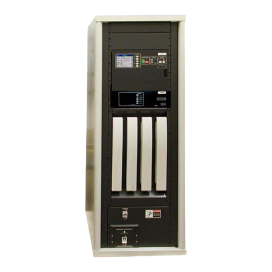
Harris Ranger Series Manuals
Manuals and User Guides for Harris Ranger Series. We have
1
Harris Ranger Series manual available for free PDF download: Commissioning Manual
Harris Ranger Series Commissioning Manual (162 pages)
Brand:
Harris
| Category:
Transmitter
| Size: 3 MB
Table of Contents
Table of Contents
13
Purpose of this Manual
17
Ranger Transmitter Models
18
System Block Diagrams
19
Transmitter Control System
21
Control System Communications
21
Graphical User Interface
21
In-System Programming or ISP
22
Remote Control
22
PA Module
22
Power Supplies
24
Apex™ Exciter
24
General Specifications
24
Introduction
27
Documentation
30
Installation Drawings
30
Installation Confirmation Checkboxes
31
Transmitter Cabinet Placement
31
Transmitter AC Connection
31
Signal and Ground Connections
33
Interlock Connections
33
External Interlocks
34
RF Mute Interlock
34
Port Patch Panel Connection Confirmation
35
Motorized RF Switch Connections (if Equipped)
36
PA and PS Module Installation
37
Initial Turn-On
38
Exciter Setup
41
Verify Exciter Signal Connections
42
AC Power
43
Verify Installation of the GPS 1PPS Signal
43
Verify Exciter Configuration
44
Verify Configuration of Setup Screens
45
Verify Configuration of FPGA Screens
46
Verify Configuration of Status Screens
47
Normal Settings for Diagnostic Screens
48
RF Initial Turn on
49
Parallel Remote Control Connections
52
Transmitter Control Functions, J13 and J14
53
Section 1 Remote Status Outputs, J15 & J16
54
Remote Power Metering, J17
56
Operation and Adjustments
57
Introduction
57
Transmitter Control Panel
57
Graphical User Interface (GUI)
58
Global Status and Navigation
59
Main Menu "Hardware" Buttons
58
GUI Home Page
60
Drive Chain Main Menu
61
Drive Meter Calibration
62
Drive Service
62
Power Amp Main Menu
63
Section 2 PA Faults
63
Module 3 Strike Routine
64
PA Faults
64
PA Meters
66
PA Data
67
PA Service
69
PA Setup (Gain Balance)
70
Output Main Menu
71
Output Service
73
Module Phasing Procedure
74
Output Setup
75
Forward and Reflected Power Calibrations
76
Power Supply Main Menu
77
AC Mains Meter Calibration
78
PS Service
78
System Main Menu
79
Control System
80
System Log
81
System Service
82
System Setup
83
Control Setup
84
System Configuration
84
Touch Screen Calibration
85
Hardware Revisions
87
Software Revisions (SW Revs)
87
GUI Menu Structures
88
RF Testing
91
Introduction
91
Proof Testing and Report
91
Report Cover Page
91
4.2.2
92
Table of Contents
92
Facilities Authorized in Construction Permit
93
Transmitter Location
93
Transmitter Manufacturer ID Plate
93
Antenna and Bandpass Filter Information
94
RF Power Summary
94
System Block Diagram
95
Test Equipment List
96
Transmitter Power Output
96
Objective
96
Requirement(S)
97
Setup and Test Equipment
97
Power Measurement Procedure
98
Power Measurement Test Results
98
Frequency Tolerance
99
Objective
99
Requirement(S)
99
Setup and Test Equipment
99
Frequency Tolerance Procedure
100
Frequency Tolerance Test Results
100
Non-Linear Precorrection
101
Objective
101
Requirement(S)
101
Response)
101
Setup and Test Equipment
101
Non-Linear Precorrection Procedure
102
Non-Linear Precorrection Test Results
103
Out of Band Emissions
103
Objective
103
Requirement(S)
104
Setup and Test Equipment
104
Out of Band Emissions Procedure
105
Out of Band Emissions Test Results
106
Spurious Emissions (Including 2Nd & 3Rd Harmonics)
109
Objective
109
Requirements
109
Setup & Test Equipment
110
Spurious Emissions Procedure
110
Spurious Emissions Test Results
112
Linear Precorrection
115
Objective
115
Requirements
115
Response)
115
Setup & Test Equipment
116
Spurious Emissions Procedure
116
Spurious Emissions Test Results
117
Linear Precorrection Procedure
120
Linear Precorrection Test Results
121
Modulation Error Ratio (MER)
122
Objective
122
Requirement(S)
122
Setup and Test Equipment
122
Modulation Error Measurement Procedure
124
Modulation Error Results
125
Meter Readings
126
System VSWR Plots
127
Software Versions
129
Appendix A - Linux Data Capture & Processing
130
Introduction
130
Required Equipment
130
Block Diagram
130
1PPS Source Setup
131
FSQ Connections
131
FSQ Settings
133
Setting Static IP Address for FSQ & Linux Machine
133
For Linux Laptop
134
For the FSQ
134
Capturing and Processing Data
135
Setting Flo Signal Parameters
135
Looking at the Results
136
Moving Results to Flash Drive
136
Performing the Measurement
136
Appendix B - Generating a CW Tone
138
Replacement Procedures
141
Introduction
141
PA Module Removal
141
CZ1000F PA Module Air Block
141
PA Module Pallet Replacement
143
Power Supply Module Replacement
146
Circulator Removal/Replacement
147
Blower Assembly Removal
149
ISP (In-System Programming)
151
Introduction
151
Installing the ISP Program
152
ISP Procedures
152
Control System ISP Procedure
153
PA Module ISP Procedure
158
Advertisement
Advertisement
Related Products
Harris RF-131
Harris RF-5000DE
Harris RF-5000
Harris RF-7800B-DUO24
Harris RF-7800W-OU49 series
Harris RF-7800W-OU470
Harris RF-7800W
Harris RF-590
Harris RF-3352
Harris RF-110A
Harris Categories
Transmitter
Amplifier
Radio
Receiver
Test Equipment
More Harris Manuals
Login
Sign In
OR
Sign in with Facebook
Sign in with Google
Upload manual
Upload from disk
Upload from URL