Nordson DuraBlue II User's Product Manual

Nordson DuraBlue II User's Product Manual

Adhesive melters
Table of Contents

Advertisement

Quick Links

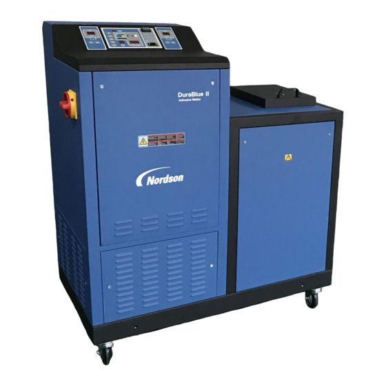
DuraBluer II Adhesive Melters
Models 20 and 45
Customer Product Manual
Part 1126931_01
Issued 08/18
This document contains important safety information.
Be sure to read and follow all safety information in this
document and any other related documentation.
NORDSON CORPORATION  DULUTH, GEORGIA  USA
www.nordson.com

Advertisement

Table of Contents
loading
Need help?

Need help?

Do you have a question about the DuraBlue II and is the answer not in the manual?

Questions and answers

Subscribe to Our Youtube Channel

Summary of Contents for Nordson DuraBlue II

  • Page 1 Models 20 and 45 Customer Product Manual Part 1126931_01 Issued 08/18 This document contains important safety information. Be sure to read and follow all safety information in this document and any other related documentation. NORDSON CORPORATION  DULUTH, GEORGIA  USA www.nordson.com...
  • Page 2 Measuring the Invisible, MEG, Meltex, MicroCoat, MicroMark, Micromedics, Micro‐Meter, Microshot, Millennium, MiniBlue, Mini Squirt, NexJet, No-Drip, Nordson, Nordson - stylized, Nordson and Arc, OptiMix, Optima, Optimum, Package of Values, Paragon, PermaFlo, PICO, Plasmod, Poly-Check, Polymer Solution Casting, Porous Coat, Posi‐Dose, PowderGrid, Precisecoat, PrintPlus, ProBlue, ProBlue Liberty, Prodigy, Pro‐Flo, Program‐A‐Bead, Program‐A‐Shot, Program‐A‐Stream, Program‐A‐Swirl, Pro‐Meter, Pulsar, Quantum,...
  • Page 3: Table Of Contents

    ......... 2‐8 Part 1126931_01 E 2018 Nordson Corporation...
  • Page 4 Monitor the Service Interval ....... . 4‐17 E 2018 Nordson Corporation Part 1126931_01...
  • Page 5 ......... . 6‐12 Part 1126931_01 E 2018 Nordson Corporation...
  • Page 6 ........7‐27 E 2018 Nordson Corporation Part 1126931_01...
  • Page 7 ......C‐5 Using Nordson Configuration Manager ......
  • Page 8 Table of Contents This page intentionally left blank. E 2018 Nordson Corporation Part 1126931_01...
  • Page 9: Safety

    CAUTION! Indicates a potentially hazardous situation that, if not avoided, can result in minor or moderate personal injury. CAUTION! (Used without the safety alert symbol) Indicates a potentially hazardous situation that, if not avoided, can result in damage to equipment or property. Issued 4-15 E 2018 Nordson Corporation...
  • Page 10: Responsibilities Of The Equipment Owner

    Provide appropriate emergency and first aid equipment. Conduct safety inspections to ensure required practices are being followed. Re‐evaluate safety practices and procedures whenever changes are made to the process or equipment. Issued 4−15 E 2018 Nordson Corporation...
  • Page 11: User Qualifications

    Do not modify the equipment. Do not use incompatible materials or unapproved auxiliary devices. Contact your Nordson representative if you have any questions on material compatibility or the use of non‐standard auxiliary devices. Issued 4-15 E 2018 Nordson Corporation...
  • Page 12: Instructions And Safety Messages

    Familiarize yourself with the location and meaning of the safety warning labels and tags affixed to the equipment. Refer to Safety Labels and Tags at the end of this section. If you are unsure of how to use the equipment, contact your Nordson representative for assistance. Installation Practices Install the equipment in accordance with the instructions provided in this document and in the documentation provided with auxiliary devices.
  • Page 13: Maintenance And Repair Practices

    Read and comply with the manufacturer's instructions and the SDS supplied with equipment cleaning compounds. NOTE: SDSs for cleaning compounds that are sold by Nordson are available at www.nordson.com or by calling your Nordson representative. Confirm the correct operation of all safety devices before placing the equipment back into operation.
  • Page 14: Equipment Shutdown

    2. Disconnect the input signal wiring to the applicator solenoid valve(s). 3. Reduce the air pressure to the applicator solenoid valve(s) to zero; then relieve the residual air pressure between the regulator and the applicator. Issued 4−15 E 2018 Nordson Corporation...
  • Page 15: General Safety Warnings And Cautions

    General Safety Warnings and Cautions Table 1‐1 contains the general safety warnings and cautions that apply to Nordson hot melt and cold adhesive equipment. Review the table and carefully read all of the warnings or cautions that apply to the type of equipment described in this manual.
  • Page 16 WARNING! Risk of fire or explosion! Nordson adhesive equipment is not rated for use in explosive environments and has not been certified for the ATEX directive or as nonincendive. In addition, this equipment HM, CA, PC should not be used with solvent‐based adhesives that can create an...
  • Page 17 CAUTION! Nordson hot melt equipment is factory tested with Nordson Type R fluid that contains polyester adipate plasticizer. Certain hot melt materials can react with Type R fluid and form a solid gum that can clog the equipment.
  • Page 18: Other Safety Precautions

    3. Do NOT attempt to remove the solidified hot melt from your skin. 4. In case of severe burns, treat for shock. 5. Seek expert medical attention immediately. Give the SDS for the hot melt to the medical personnel providing treatment. Issued 4−15 E 2018 Nordson Corporation...
  • Page 19: Safety Labels And Tags

    [Tag, warning, hazardous volts] WARNING: Hazardous voltage. Disconnect all power supply connections before servicing. 224906 [Tag, warning, electrical shock] 224905 [Tag, warning, hot] 1025326 [Tag, caution, hot surface] 1021983 [Tag, warning, hot adh/hyd press] Issued 4-15 E 2018 Nordson Corporation...
  • Page 20 1-12 Safety Issued 4−15 E 2018 Nordson Corporation...
  • Page 21: Introduction

    II adhesive melters may be used only to melt and convey suitable materials, e.g. thermoplastic hot melt adhesives. Any other use is considered to be unintended. Nordson will not be liable for personal injury or property damage resulting from unintended use.
  • Page 22: Examples Of Unintended Use

    Risk of damage to cables/lines belonging to the customer, if they were installed such that they come into contact with hot or rotating parts. The safety valve may malfunction due to hardened or charred material. E 2018 Nordson Corporation Part 1126931_01...
  • Page 23: Key Components

    1 Control panel (see Figure 2‐3) 5 Motors/pumps 9 Hose receptacles 2 Protective panel, removable 6 Drain valve 10 ID plate 3 Tank lid 7 Pressure control valve 11 Tank 4 Main power switch 8 Manifold Part 1126931_01 E 2018 Nordson Corporation...
  • Page 24: Electrical Components

    6 Signal conditioner 10 Distribution block 3 Solid state relay 7 Expansion board 11 Contactor 4 Fan 8 Power module Note: The central processing unit is not shown in this illustration. Refer to Section 7, Parts. E 2018 Nordson Corporation Part 1126931_01...
  • Page 25: Control Panel

    9 Setup key/LED 15 Right display and arrow keys 4 Pump enable key/LED 10 Fault light 16 Numeric keypad 5 Standby key/LED 11 Ready light 17 Serial port 6 Master pump enable key/LED 12 Component keys/LEDs Part 1126931_01 E 2018 Nordson Corporation...
  • Page 26: Tank Isolation Valve

    The tank isolation valve allows replacement of the pump without first emptying the tank. Figure 2‐4 Location of the tank isolation valve Pressure Control Valves The manual pressure control valves can be adjusted from 0-90 bar. Figure 2‐5 Location of the pressure control valves E 2018 Nordson Corporation Part 1126931_01...
  • Page 27: Modes Of Operation

    Introduction Modes of Operation DuraBlue II adhesive melters operate in the following modes. Automatic Scan (Normal Mode) The melter automatically checks and displays the current temperature of the tank, hoses, and guns to confirm that they are within their pre‐defined temperature range.
  • Page 28: Melter Identification

    The model and part number are indicated on the equipment identification plate that is located on the front of the melter. Figure 2‐6 Location of the melter identification plate E 2018 Nordson Corporation Part 1126931_01...
  • Page 29: Installation

    Procedural variations or special considerations are explained in the additional information table that follows most procedures. Where applicable, some table entries also contain cross‐reference information. Additional information tables are indicated by the symbol shown to the left. Part 1126931_01 E 2018 Nordson Corporation...
  • Page 30: Installation Tasks

    Before installing the melter, ensure that the desired installation location provides the required clearances, environmental conditions, and utilities. Clearances Figure 3‐1 illustrates the minimum clearances that are required between the melter and surrounding objects. E 2018 Nordson Corporation Part 1126931_01...
  • Page 31 Installation Minimum Installation Clearances 118 in. (3000 mm) OPERATION SPACE 41.5 in. (1054.5 mm) 6.6 in. (167 mm) Figure 3‐1 Melter minimum installation clearances Part 1126931_01 E 2018 Nordson Corporation...
  • Page 32: Ventilation

    Installation Ventilation DuraBlue II melters are cooled by forced air. Air is drawn in through by the ventilation fan and is exhausted out of the ventilation slots at the top of the melter. CAUTION! Do not block the fan air intake openings or the exhaust ventilation slots.
  • Page 33: Other Considerations

    The melter must be installed where it will be in conformance with the ventilation requirements specified in the Safety Data Sheet for the hot melt being used. The melter should not be exposed to excessive vibration. Part 1126931_01 E 2018 Nordson Corporation...
  • Page 34: Unpacking The Melter

    Before starting the installation, remove the melter from the pallet, locate the installation kit, and inspect the melter for damaged and missing parts. Report any problems to your Nordson representative. Moving the Unpacked Melter When moving the melter, always support the melter by placing any lifting device under the chassis.
  • Page 35: Configuring The Electrical Service

    Installation Configuring the Electrical Service DuraBlue II melters are shipped from the factory without an attached power cable. To configure the melter to function in your facility, you must connect a properly rated power cable. The maximum power draw of the melter for any supported service code is 86 A.
  • Page 36 Installation Connecting the Electrical Service (contd) Table 3‐1 Electrical Service Wiring Terminals Line voltage 400 V 3‐phase with neutral (star ‐ WYE) 400V-XL0 Figure 3‐3 Location of service wiring strain relief and terminal block E 2018 Nordson Corporation Part 1126931_01...
  • Page 37: Connecting Hoses And Applicators

    Replacement Parts Catalog or contact your Nordson representative. Refer to the user's guide provided with each Nordson hose. The guide contains important information about routing and installing the hose. Save all of the port plugs removed from the manifold. A port plug will need to be reinstalled into the manifold if a hose is later removed.
  • Page 38 3-10 Installation Connect Hoses (contd) Pump 1: Output port 1 Pump 1: Output port 2 Figure 3‐4 Connecting hoses E 2018 Nordson Corporation Part 1126931_01...
  • Page 39 3-11 Installation Connect Hoses (contd) HC−H6 HC−H5 HC−L4 HC−L3 HC−L2 HC−L1 Figure 3‐5 Connecting a hose cordset Part 1126931_01 E 2018 Nordson Corporation...
  • Page 40: Connect Applicators

    NOTE: DuraBlue II adhesive melters are shipped with a 0.2 mm hot melt filter installed in the manifold. Order the appropriate applicator nozzle based on this filter mesh size.
  • Page 41: Setting Up The Melter

    If you need to make changes to the factory setup or if you want to learn about other operating parameters, go to the next part in this section, Operating Parameters. Part 1126931_01 E 2018 Nordson Corporation...
  • Page 42 A group of parameters that control the melter's clock. 50 to 77 Seven‐day Clock The clock is used to automatically turn the heaters on Disabled and off and to place the melter into the standby mode. E 2018 Nordson Corporation Part 1126931_01...
  • Page 43: Operating Parameters

    NOTE: Parameters that are used to configure optional equipment or that are otherwise reserved in the firmware are excluded from Table 3‐4 and Appendix B. Part 1126931_01 E 2018 Nordson Corporation...
  • Page 44: Reading Or Editing Operating Parameters

    The melter checks that the new value or control option is acceptable. If the numeric set‐point or control option is accepted, the left and right displays index to the next sequential parameter number and value. E 2018 Nordson Corporation Part 1126931_01...
  • Page 45 1 (Standby on/off) Standard Input 3 0–8 and 10-14 2 (Heaters on/off) Standard Input 4 4 (Hose/applicator 1 0–8 and 10-14 enable/disable) Optional Input 5 0–8 and 10-14 0 (disabled) Not used with DuraBlue II melters. Part 1126931_01 E 2018 Nordson Corporation...
  • Page 46 —:— Schedule 3 Heaters On 0000 to 2359 —:— Schedule 3 Heaters Off 0000 to 2359 —:— Schedule 3 Enter Standby 0000 to 2359 —:— Schedule 3 Exit Standby 0000 to 2359 —:— Continued… E 2018 Nordson Corporation Part 1126931_01...
  • Page 47 If password protection is enabled, the melter Appendix B, Parameter 10 will return to the password protected mode whenever you exit the setup mode. Part 1126931_01 E 2018 Nordson Corporation...
  • Page 48: Set-Point Temperature Of The Tank, Hoses, And Applicators

    Adjusting Component Temperatures in Section 4, Operation. As with operating parameters, you can also save and restore set‐point temperatures and review past changes that were made to set‐point temperatures. E 2018 Nordson Corporation Part 1126931_01...
  • Page 49 Each component begins to heat or cool to the new global set‐point temperature and the melter returns to the automatic scan mode. When all of the components reach the global set‐point temperature, the Enter key ready LED turns on (green). Ready LED Part 1126931_01 E 2018 Nordson Corporation...
  • Page 50: Save And Restore Melter Settings

    This will cause the hoses and applicators to stop heating. You can transfer melter settings from one Refer to Appendix C, Melter melter to another using the Nordson Communications Configuration Manager software utility. E 2018 Nordson Corporation Part 1126931_01...
  • Page 51: Review Parameter And Set-Point Temperature Changes

    3. Press a right‐display scroll key to review each of the remaining nine log entries. Each press of a scroll key displays a progressively older log entry. 4. Press the Setup key to return to the automatic scan mode. Scrolling through the log Part 1126931_01 E 2018 Nordson Corporation...
  • Page 52 Parameter 4 (ready delay) was changed. Example 2: If the LED on the applicator key is on, then this display would indicate that the global‐by‐component method was used to change the temperature of the applicators. E 2018 Nordson Corporation Part 1126931_01...
  • Page 53: Setting Up Inputs/Outputs

    Setting Up Inputs/Outputs DuraBlue II adhesive melters are equipped with four standard inputs. Each input is customer‐wired to the melter and then set up to provide one of the following control options:...
  • Page 54: Wire Inputs/Outputs To The Melter

    2. Connect each pair of input and output wires to the appropriate terminals on terminal block XI. Refer to Table 3‐6 for the terminal numbers that correspond to each input. Figure 3‐6 Location of the XI terminal block for connecting input/output wiring E 2018 Nordson Corporation Part 1126931_01...
  • Page 55: Set Up Inputs/Outputs

    5 - Hose/Applicator 2 Enable/Disable 6 - Hose/Applicator 3 Enable/Disable 7 - Hose/Applicator 4 Enable/Disable 8 - Hose/Applicator 5 Enable/Disable 9 - Hose/Applicator 6 Enable/Disable 10 – Automatic standby (Default) 11 - Motor 2 Enable/Disable Continued... Part 1126931_01 E 2018 Nordson Corporation...
  • Page 56 31. Parameters are disabled in DuraBlue II adhesive melters. Refer to parameters 9-12 in this table. If control option 10 is selected for input 1, a time must be set in parameter 24.
  • Page 57 Motor 2 — XI:21, XI:22 Connect a remote start momentary, normally open contact to the terminals. Motor 2 — XI:23, XI:24 Connect a remote stop momentary, normally open contact to the terminals. Continued... Part 1126931_01 E 2018 Nordson Corporation...
  • Page 58 (optional) Up Motor Run Status Monitoring. (See Note J) Motor drive 4 — XI:39, XI:40 running (optional) (See Note J) J: Motors 3 and 4 are present only on three/four pump or 100L melters. E 2018 Nordson Corporation Part 1126931_01...
  • Page 59: Setting Up Gear-To-Line Operation

    The AltaBlue motor control accepts a 0-10 VDC analog input signal. NOTE: Nordson offers a 0-10 VDC line‐speed signal generator. Refer to Optional Accessories in Section 7, Parts, for the part number.
  • Page 60: Setting Up Motor Run Status Monitoring

    An explanation of the keypad button functions is given in the following table. Keypad Buttons Description Menu navigation (UP/Down). Adjust parameter values. Analog Input 1 Enter (sub-) menu/parameter. PAR 430 Confirm parameter. AUTO Exit (sub-) menu/parameter. Stop inverter Release inverter E 2018 Nordson Corporation Part 1126931_01...
  • Page 61: Programming

    (ENT) to select the sub parameter. 6. Press (UP) to select P420.01. 7. Press (ENT) to set parameter. 8. Press (UP) to change parameter until 51 is displayed. 9. Press (ENT) >3S to save parameters to memory. Part 1126931_01 E 2018 Nordson Corporation...
  • Page 62: Installing Optional Equipment

    Refer to Section 4, Operation, for information about filling the tank and operating the melter. Disposing of Melter When your Nordson product has reached the end of its useful life, dispose of it in accordance with local regulations. E 2018 Nordson Corporation...
  • Page 63: Operation

    Procedural variations or special considerations are explained in the additional information table that follows most procedures. Where applicable, some table entries also contain cross‐reference information. Additional information tables are indicated by the symbol shown to the left. Part 1126931_01 E 2018 Nordson Corporation...
  • Page 64: Filling The Tank

    (or otherwise identify) the auxiliary device as to the hose or applicator position number that represents the device. The control panel will identify such devices as a hose or applicator, regardless of what the device actually is. E 2018 Nordson Corporation Part 1126931_01...
  • Page 65: Starting The Melter

    Turns on the ready LED (green) when the tank and all of the hoses and applicators are within 3 _C (5 _F) of their assigned set‐point temperature. Heaters LED Automatic scan sequence Ready LED Part 1126931_01 E 2018 Nordson Corporation...
  • Page 66 Operation Starting the Melter (contd) CAUTION! Do not operate Nordson pumps without material. Before enabling the motor(s), ensure that the tank is filled. 3. Press the master pump enable key to enable the pump(s). The LED on the key turns yellow to indicate that a pump is enabled, but not running.
  • Page 67 If the seven‐day clock was on prior to the power failure, the melter will restart in the mode dictated by the clock schedule at the time the melter restarts. Part 1126931_01 E 2018 Nordson Corporation...
  • Page 68: Manually Adjusting The Pump Speed

    (1%, 1 rpm, 0.5 rpm, etc.) upon each press of an arrow key by changing the value of the motor control SEt parameter. Refer to Changing a Motor Control Parameter in Section 6, Troubleshooting. Pump speed arrow keys E 2018 Nordson Corporation Part 1126931_01...
  • Page 69: Adjusting Material Pressure

    To adjust the pressure, loosen the set screw, and then turn the pressure adjustment screw clockwise. When the pressure adjustment is set to its full counterclockwise position, 100% of the material is re‐circulated. Pressure control valves Part 1126931_01 E 2018 Nordson Corporation...
  • Page 70: Monitoring The Melter

    If the clock has placed the melter into the standby mode, pressing the standby key will return the heated components to their assigned set‐point temperature. E 2018 Nordson Corporation Part 1126931_01...
  • Page 71: Monitor Component Temperatures

    The right display indicates the actual temperature of the selected component. Component temperature display 3. Press the Setup key twice to return to the automatic scan mode. Part 1126931_01 E 2018 Nordson Corporation...
  • Page 72 UP scroll key. Holding down the scroll key while the melter is in the automatic scan mode reveals the set‐point of each component that is scanned. E 2018 Nordson Corporation Part 1126931_01...
  • Page 73: Monitor Melter Faults

    Replace CPU failure persists Heaters remain on, Internal clock Battery‐backed RAM F4/5 but fault condition Replace CPU battery battery dead persists Melter stops RTD analog‐to‐digital Replace main board or F4/6 Analog‐to‐digital functioning converter failed Continued... Part 1126931_01 E 2018 Nordson Corporation...
  • Page 74 2. The LED on the affected component key (tank, hose, or applicator) turns on to indicate the type of component that has, or is, failing. 3. The right display indicates the type of fault (F1, F2, or F3). E 2018 Nordson Corporation Part 1126931_01...
  • Page 75 OP, the RTD is open, if it indicates SH, the RTD has shorted. If, for any reason, a component reaches 235 _C (458 _F), an immediate F3 fault will occur (no two‐minute monitoring period). Part 1126931_01 E 2018 Nordson Corporation...
  • Page 76 3. Press the Clear/Reset key. 4. Press the Heater key to turn on the heaters. Heater key If F4 appears in the right display when you press the clock key, the internal clock function has failed. E 2018 Nordson Corporation Part 1126931_01...
  • Page 77 2 = Component under temperature 4 = Hose 4 or applicator 4 3 = Component over temperature 4 = Processor or electrical failure 5 = Hose 5 or applicator 5 6 = Hose 6 or applicator 6 Part 1126931_01 E 2018 Nordson Corporation...
  • Page 78 When an F1 fault is the result of a hose/applicator pair being disconnected from the melter, two fault log entries are created. The first entry is for the applicator and the second entry is for the hose. E 2018 Nordson Corporation Part 1126931_01...
  • Page 79: Monitor The Service Interval

    With the melter in the scan mode, press the Clear/Reset key to turn off the service LED and reset the service interval time. Clear/Reset key The default setting for the service interval time is 500 hours, refer to Parameter 5 in Appendix B. Part 1126931_01 E 2018 Nordson Corporation...
  • Page 80: Adjusting Component Temperatures

    5. Press the Tank key. All components begin to heat or cool to the new global set‐point temperature. When all of the components reach their set‐point temperature, the ready LED turns on (green). Ready LED E 2018 Nordson Corporation Part 1126931_01...
  • Page 81 Refer to Entering a Password in this section. 5. Press the Enter key. The hoses or the applicators begin to heat or cool to their new set‐point temperature. Part 1126931_01 E 2018 Nordson Corporation...
  • Page 82 To register the new set‐point temperature and return to the automatic scan mode, go to step 6. 6. Press any component key (tank, hose, or applicator). The selected component begins to heat or cool to its new set‐point temperature. E 2018 Nordson Corporation Part 1126931_01...
  • Page 83 Parameter and Set‐point parameters) in the change history log. Temperature Changes You can save set‐point temperature changes by Section 3, Installation, Save and simultaneously pressing the 1 key and the Setup key. Restore Melter Setting Part 1126931_01 E 2018 Nordson Corporation...
  • Page 84: Entering A Password

    Setup key twice. The melter password is created and Setting Up the Melter in Section 3, enabled/disabled during system setup. Installation E 2018 Nordson Corporation Part 1126931_01...
  • Page 85: Using Function Keys

    If the pump is enabled, but the input voltage is not present, the master pump enable key LED will flash green. Part 1126931_01 E 2018 Nordson Corporation...
  • Page 86: Setup Key

    The clock will still operate when the melter is faulting or is in the setup mode. If F4 appears in the right display when you press Section 7, Troubleshooting the clock key, the internal clock function has failed. E 2018 Nordson Corporation Part 1126931_01...
  • Page 87: Standby Key

    The melter may also be set up to automatically Appendix B, Parameters 25, 26, 57, enter the standby mode using a variety of 30–33, 62, and 67 operating parameters. Whenever manual standby is enabled, the standby Appendix B, Parameter 26 LED blinks. Part 1126931_01 E 2018 Nordson Corporation...
  • Page 88: Shutting Down The Melter

    3. Place the main power switch in the OFF position. 4. Disable the applicators as follows: Air‐operated applicators: turn off the air supply to the applicators. Electric applicators: turn off the applicator driver, pattern controller, or timer. E 2018 Nordson Corporation Part 1126931_01...
  • Page 89: Record Of Melter Settings

    4-27 Operation Record of Melter Settings Production information: Material: Manufacturer Processing Temperature Viscosity Cleaning agent: Manufacturer Flash point Processing temperatures (Setpoint temperatures): Tank/Grid/Reservoir Hose Applicator Pump speeds: Pump Notes: Name Date Part 1126931_01 E 2018 Nordson Corporation...
  • Page 90 4-28 Operation This page intentionally left blank. E 2018 Nordson Corporation Part 1126931_01...
  • Page 91: Service

    3. Activate the solenoid valve(s) electrically or manually; or, pull the trigger of the assembly hand‐held applicator. Repeat this procedure until no more material flows out. 4. Re‐use the material or properly dispose of it according to local regulations. Part 1126931_01 E 2018 Nordson Corporation...
  • Page 92 3. Open all the drain valves. Adhesive will drain from the valves. 4. When adhesive stops draining, close the drain valves. 5. Re‐use the material or properly dispose it of according to local regulations. Figure 5‐1 Location of the melter drain valves E 2018 Nordson Corporation Part 1126931_01...
  • Page 93: Preventive Maintenance Schedule

    Disassemble and clean filter cartridge Recommendation: Every 1000 hours of operation Tank Clean tank by hand When there is material residue in Cleaning the Tank tank Tighten fixing screws Every 500 hours of operation Part 1126931_01 E 2018 Nordson Corporation...
  • Page 94: Changing The Material Type

    Open the protective panels with a 4 mm Allen key. On the inside Fan and Air Filter The air filters must be cleaned (knocked out) or replaced, depending on dust accumulation. Refer to Section 7, Parts, for the filter part number. E 2018 Nordson Corporation Part 1126931_01...
  • Page 95: Motor And Gear Box

    Degol BMB 220 or Degol BG 220 Energol GR‐XP 220 Falcon CLP 220 ESSO Spartan EP 220 or GP 90 KLÜBER Klüberoil GEM 1‐220 OPTIMOL Optigear 220 SHELL Omala Oil 220 TEXACO Geartex EP‐A SAE 85 W‐90 Part 1126931_01 E 2018 Nordson Corporation...
  • Page 96: Replacing A Motor Or Coupling

    4. See Figure 5‐2. Loosen the screws that secure the motor to the base of the melter and then slide the motor back. 5. Slide the coupling sleeve (2) off of the coupling hubs (1 and 3), loosen the hub set screws, and remove the hubs. E 2018 Nordson Corporation Part 1126931_01...
  • Page 97 9. Ensure that the coupling sleeve cannot move, then slide the motor assembly back 4 mm (0.16 in.), as indicated in Figure 5‐3. Part 1126931_01 E 2018 Nordson Corporation...
  • Page 98: Pump

    2. Ensure that the melter, tank, manifold, and pump are cold. 3. See Figure 5‐4. Tighten the screws to 25 NSm (222 in.‐lb). Figure 5‐4 Tightening the pump screws 4. Restore the system to normal operation. E 2018 Nordson Corporation Part 1126931_01...
  • Page 99: Replacing A Pump

    O‐rings O‐ring lubricant anti‐seize lubricant NOTE: To rebuild a pump, contact your Nordson representative for assistance. 1. Ensure the melter is at operating temperature. 2. Relieve system pressure. Refer to Section 1, Safety. 3. See Figure 5‐5. Close the tank isolation valve.
  • Page 100 7. Slide the coupling sleeve (2) off of the coupling hubs (1 and 3), loosen the pump coupling hub set screws, and remove the pump coupling hub. Figure 5‐6 Coupling assembly components 1 Motor coupling hub 3 Pump coupling hub 2 Coupling sleeve E 2018 Nordson Corporation Part 1126931_01...
  • Page 101 13. Apply anti‐seize lubricant to the pump screws and secure the new pump to the manifold with the screws. Use a torque wrench to tighten the screws in a criss‐cross manner to 25 NSm (222 in.‐lb). Part 1126931_01 E 2018 Nordson Corporation...
  • Page 102 17. To ensure proper motor and pump shaft alignment, verify that you can freely slide the coupling sleeve back and forth by about 4 mm (0.16 in.) each way. 18. Restore the system to normal operation. E 2018 Nordson Corporation Part 1126931_01...
  • Page 103: Replacing The Adhesive Filter

    Service Replacing the Adhesive Filter DuraBlue II melters are equipped with a 100-mesh (0.15-mm) disposable hot melt adhesive filter. The adhesive filter removes debris and char from the hot melt as it flows from the tank. Hot melt flows from the inside to the outside of the filter, trapping contaminants inside the filter.
  • Page 104: Replace The Adhesive Filter

    5. Screw the filter into the pump body and then tighten the filter to 4.5 Nm (40 in.-lb). 6. Resume normal operation. Service Kit, for P/N refer to Section 7, Parts. Figure 5‐9 Turning the adhesive filter counterclockwise to remove E 2018 Nordson Corporation Part 1126931_01...
  • Page 105: Pressure Control Valve

    7. Slide the valve into the hole and tighten with torque wrench (15 N•m / 133 in.-lb). 8. Adjust the setting screw to the recorded dimension X. Turning to the right increases material pressure. Turning to the left decreases material pressure. Adjusting the set screw Part 1126931_01 E 2018 Nordson Corporation...
  • Page 106: Pressure/Circulation Control Valve Service Kit

    Install new O‐rings. Apply grease to all threads and O‐rings. Guide pressure control valve into the hole when the melter is warm and tighten with torque wrench. Starting torque: 15 NSm (133 in.‐lb) Adjust set screw. Refer to Pressure Control Valve. E 2018 Nordson Corporation Part 1126931_01...
  • Page 107: Cleaning The Tank

    Tighten screws as indicated in the table below. NOTE: Tighten fixing screws only using a torque wrench and when the melter is cold. Connection Thread Torque Tank/manifold 6-8 NSm / 53-71 in.‐lb Part 1126931_01 E 2018 Nordson Corporation...
  • Page 108: Main Pca Board

    Figure 5‐12 shows the location of terminal JP1 on the main PCA board. Figures 5‐13 and 5‐14 show the jumpers installed and not installed, as appropriate for each type of melter. E 2018 Nordson Corporation Part 1126931_01...
  • Page 109 R132 R131 R123 R136  F5 6.3A 6.3A DS14 6.3A 6.3A 6.3A   6.3A R116 DS10 DS11 DS12 R106   C71 DS13 R104 Figure 5‐12 Location of the JP1 terminal on the main PCA board Part 1126931_01 E 2018 Nordson Corporation...
  • Page 110 8. Reconnect all of the power and control cables to the replacement board and close the electrical access panel. 9. Restore power to the melter and switch the melter on. Verify that the melter starts normally. E 2018 Nordson Corporation Part 1126931_01...
  • Page 111: Maintenance Record Form

    Service Maintenance Record Form Melter part Date / Name Date / Name Date / Name Pump Motor / gear box Fixing screws on pump and tank Air filter Tank Pressure control valve Filter cartridge Part 1126931_01 E 2018 Nordson Corporation...
  • Page 112 5-22 Service E 2018 Nordson Corporation Part 1126931_01...
  • Page 113: Troubleshooting

    If the melter is removed from its sub‐base for diagnostic checks or service, ensure that the ground lead between the chassis and the sub‐base is re‐attached when the melter is reconnected to the sub‐base. Part 1126931_01 E 2018 Nordson Corporation...
  • Page 114: Troubleshooting Quick-Checks

    To return the melter to its factory settings, simultaneously press and hold the Setup key and the right‐display DOWN arrow key, and then, while holding down these keys, cycle the control switch off and on. When the melter restarts, release the two keys. E 2018 Nordson Corporation Part 1126931_01...
  • Page 115: Melter Faults

    Replace CPU failure persists Heaters remain on, Internal clock Battery‐backed RAM F4/5 but fault condition Replace CPU battery battery dead persists Melter stops RTD analog‐to‐digital Replace main board or F4/6 Analog‐to‐digital functioning converter failed Continued... Part 1126931_01 E 2018 Nordson Corporation...
  • Page 116 CPU and the card persists optional I/O card Alert output (if output Fieldbus option 6 is selected) Replace the Fieldbus F4/E communications Fieldbus card failure. Melter continues to card failure operate normally. E 2018 Nordson Corporation Part 1126931_01...
  • Page 117: Motor Control Faults

    Refer to Calibrating the Pump Speed Display. Motor control not operating as Improper motor control Check motor control parameter expected parameter settings settings. Refer to Changing a Motor Control Parameter in this section. Part 1126931_01 E 2018 Nordson Corporation...
  • Page 118: Changing A Motor Control Parameter

    4. Use the Pump speed arrow keys to select a value for the parameter shown on the pump speed display. Refer to Table 6‐3 for a parameter list. Pump speed arrow keys E 2018 Nordson Corporation Part 1126931_01...
  • Page 119 0. If the melter will operated in the gear‐to‐line mode, enter a minimum line speed. The motor speed will not fall below this valve even if the signal drops to 0 V. Part 1126931_01 E 2018 Nordson Corporation...
  • Page 120: Motor Drive Faults

    Figure 6‐1 Motor drive power LED and display 1. Motor drive Ready (RDY) LED 2. Motor drive Error (ERR) LED E 2018 Nordson Corporation Part 1126931_01...
  • Page 121: Led Status Display

    Motor drive inhibited, DC Voltage not On OR Reset Motor drive inhibited, Warning active Motor drive inhibited, Fault active – Motor drive released, drive running OR Quick Stop Motor drive released, drive running, Warning active Motor drive released, Trouble reaction active Part 1126931_01 E 2018 Nordson Corporation...
  • Page 122: Motor Drive Error History

    The following figure explains each component in the Error History data: Figure 6‐2 Explanation of the Error History data NOTES: Press to toggle between two screens. Press to navigate from Error 01 to Error 32. E 2018 Nordson Corporation Part 1126931_01...
  • Page 123 6-11 Troubleshooting The following is an example of how to navigate Error History : Figure 6‐3 Navigating Error History Part 1126931_01 E 2018 Nordson Corporation...
  • Page 124: Error Messages

    Fault F.AL Assertion level fault 0x8100 33024 Configurable CAN bus off CAN bus off 0x8101 33025 Configurable CAN bus warning CAN warning 0x8109 33033 Configurable Stack init error Fieldbus communication stack initialization error Continued... E 2018 Nordson Corporation Part 1126931_01...
  • Page 125 Test monitor generated fault with fault reset blocked 0xFF48 65352 Fault Safety fault Safety supervision fault 0xFF49 65353 Fault EPM invalid data EPM contains invalid user data 0xFF50 65360 Fault EPM not present EPM not present Continued... Part 1126931_01 E 2018 Nordson Corporation...
  • Page 126 AC control user fault 0xFF85 65413 Fault Netwrk user flt1 Network user fault 1 0xFF86 65414 Fault Netwrk user flt2 Network user fault 2 0xFF87 65415 Fault NetWordIN1 Setup NetwordIN1 duplicate bit connection fault E 2018 Nordson Corporation Part 1126931_01...
  • Page 127: Changing A Motor Drive Parameter

    AUTO – Up/Down arrows are inactive (speed control is external) SET8 – The blinking indicates that a setting or value has changed and needs to be entered. Once the settings are saved, the icon is steady Part 1126931_01 E 2018 Nordson Corporation...
  • Page 128 Network setup menu Basic setup Process control menu Motor setup Auxiliary function menu The favorites menu contains links to the most commonly used parameters for initial commissioning and monitoring of the motor drive for general applications. E 2018 Nordson Corporation Part 1126931_01...
  • Page 129: Favorites Group Navigation

    Groups Screen Press Favorites GROUP 0 NOTE: Use the Up and Down buttons to SETS AUTO navigate to other groups. In this example, the BACK button is used to return to the Operating Screen. Continued... Part 1126931_01 E 2018 Nordson Corporation...
  • Page 130: Saving The Settings

    After the adjustments are complete, press for three (3) seconds to save all the settings to memory. AUTO SET8 icon blinks when the settings are not saved. Once the settings are saved, the icon is steady. VEL:FLEX:AIN1 PSAVED AUTO E 2018 Nordson Corporation Part 1126931_01...
  • Page 131: Navigation Group

    (3) seconds to save all the settings to memory. AUTO SET8 icon blinks when the settings are not saved. Once the Press > 3S (Saving Parameter) settings are saved, the icon is steady. VEL:FLEX:AIN1 PSAVED AUTO Part 1126931_01 E 2018 Nordson Corporation...
  • Page 132: Motor Drive Parameter Factory Settings

    GROUP3 P315:01 Slip Compensation GROUP3 P320:04 Motor Speed 1350 GROUP3 P320:05 Motor Frequency GROUP3 P320:06 Motor Power 0.25 GROUP3 P320:07 Motor Voltage GROUP3 P320:08 Motor cos PHi GROUP4 P430:03 Frequency at max signal 102Hz E 2018 Nordson Corporation Part 1126931_01...
  • Page 133: Calibrating The Pump Speed Display

    2. Press and hold both Pump speed arrow keys. 3. When the pump speed display indicates CAL, release the keys. 4. Enter the actual pump rpm. Pump speed arrow keys 5. Press the Pump mode key. Pump mode key and LED Part 1126931_01 E 2018 Nordson Corporation...
  • Page 134: Troubleshooting Tables

    Possible Fault / Troubleshooting Corrective Action Channel is disabled / — Enable / switch on switched off Control Panel Does Not Function Problem Possible Cause Corrective Action Display is blank SPS broad‐band cable not Connect connected E 2018 Nordson Corporation Part 1126931_01...
  • Page 135: No Material (Motor Does Not Rotate)

    Clean cooling section of motor controller Short circuit Check motor cable Overload (pump blocked by foreign Refer to 6. matter, pump too sluggish, material too cold) 10. Motor drive defective — Replace Part 1126931_01 E 2018 Nordson Corporation...
  • Page 136: No Material (Motor Rotating)

    Correct temperature setting temperature set too Pump block is worn — Replace pump Safety valve defective — Replace safety valve Pump defective — Replace pump Pressure control — Adjust pressure control valve valve setting too low E 2018 Nordson Corporation Part 1126931_01...
  • Page 137: Material Pressure Too High

    Pressure control — Disassemble and clean or replace valve dirty and thus clogged Pressure control — Replace valve defective Pressure control — Set to default valve set incorrectly Part 1126931_01 E 2018 Nordson Corporation...
  • Page 138: Material Residue In Tank

    Processed material too cold Correct temperature setting (observe data sheet of material manufacturer) Foreign material in pump Replace pump Leakage at gun Safety valve does not open Replace safety valve during heat‐up phase (expansion pressure) E 2018 Nordson Corporation Part 1126931_01...
  • Page 139: Parts

    Item—Identifies illustrated parts that are available from Nordson Corporation. Part—Provides the Nordson Corporation part number for each saleable part shown in the illustration. A series of dashes in the parts column (‐ ‐ ‐ ‐ ‐ ‐) means the part cannot be ordered separately.
  • Page 140: Melter Part Numbers

    Parts Melter Part Numbers Part Description 7401355 DuraBlue II,20L,SN0773,6HG,NI,400V WYE 7401356 DuraBlue II,45L,SN0773,6HG,NI,400V WYE E 2018 Nordson Corporation Part 1126931_01...
  • Page 141: Frame Assembly

    Item Part Description Quantity Note ‐ ‐ ‐ ‐ ‐ ‐ ‐ MODULE,ENCL,1 MOTOR,DURABLUE II ‐ ‐ ‐ ‐ ‐ ‐ ‐ CTL BOX,1 M,WITH FRONT PANEL, DURABLUE II ‐ ‐ ‐ ‐ ‐ ‐ ‐ PANEL,MOTORS CHAMBER,LEFT,EZ ‐ ‐ ‐ ‐ ‐ ‐ ‐...
  • Page 142: Manifold Assembly

    S WASHER,FLT,M,OVERSIZED,6,STL,Z ‐ ‐ ‐ ‐ ‐ ‐ ‐ S SAFETY VALVE 85 BAR VB/DB FIX 207932 S KIT,CORDSTOCK,3MM OD,VITON,75D 1058990 S THERMOSTAT,OOR,500DEG F,PUSH-ON 1024618 TERM S PLATE, CAPTURE, RTD 1030564 S COVER,BOTTOM,MANIFOLD,EZ 7411485 E 2018 Nordson Corporation Part 1126931_01...
  • Page 143 Parts Figure 7‐2 Manifold assembly parts Part 1126931_01 E 2018 Nordson Corporation...
  • Page 144: Melter Hopper Parts

    ‐ ‐ ‐ ‐ ‐ ‐ ‐ S SCR, SHCS, M4 X 6, BL ‐ ‐ ‐ ‐ ‐ ‐ ‐ S PLATE, CAPTURE, RTD 1030564 S COMPOUND, HEAT SINK,5 OZ TUBE 900298 S INSULATION,HOPPER,EZ,20L 7410542 E 2018 Nordson Corporation Part 1126931_01...
  • Page 145 Parts 215 206 209 207 212 211 Figure 7‐3 Melter hopper assembly parts (20L hopper shown) Part 1126931_01 E 2018 Nordson Corporation...
  • Page 146: Pump Assemblies

    S LUBRICANT, NEVER SEEZ, 8 OZ CAN 900344 ‐ ‐ ‐ ‐ ‐ ‐ ‐ S DUAL STREAM GEAR PUMPS NOTE A: Refer to Motor Assembly Parts. B: Refer to Gear Pumps Parts. Figure 7‐4 Pump module parts E 2018 Nordson Corporation Part 1126931_01...
  • Page 147: Single-Stream Gear Pumps

    Parts Single‐Stream Gear Pumps See Figure 7‐5. Item Part Description Quantity Note — 729107 GEAR PUMP SN0773 Figure 7‐5 Single‐stream gear pumps Part 1126931_01 E 2018 Nordson Corporation...
  • Page 148: Safety Valve Parts

    S O‐RING 11 X 2 ‐ ‐ ‐ ‐ ‐ S O‐RING 9 X 2 ‐ ‐ ‐ ‐ ‐ S HIGH‐TEMP. GREASE, GLS 595/N2, 10G — ‐ ‐ ‐ ‐ ‐ Figure 7‐6 Safety valve parts E 2018 Nordson Corporation Part 1126931_01...
  • Page 149: Control Valve Assemblies

    — ‐ ‐ ‐ ‐ ‐ ‐ ‐ PLUG, PRESSURE REGULATOR VALVE VB/DB NOTE A: Refer to Pressure Control Valve Parts. B: Refer to Circulation Control Valve Parts. Figure 7‐7 Pressure control module parts Part 1126931_01 E 2018 Nordson Corporation...
  • Page 150: Filter Cartridge Parts

    Parts Filter Cartridge Parts See Figure 7‐8. Item Part Description Quantity Note 1031235 FILTER, WITH O-RING, 50-MESH — 1028305 FILTER, WITH O-RING, 100-MESH — 1031236 FILTER, WITH O-RING, 200-MESH Figure 7‐8 Filter cartridge parts E 2018 Nordson Corporation Part 1126931_01...
  • Page 151 ‐ ‐ ‐ ‐ ‐ S O‐ring 9 x 2 ‐ ‐ ‐ ‐ ‐ S High‐temp. grease, GLS 595/N2, 10 g — ‐ ‐ ‐ ‐ ‐ Figure 7‐9 Pressure control valve parts Part 1126931_01 E 2018 Nordson Corporation...
  • Page 152: Motor Assembly

    S WASHER, FLT, M, REG, M8, STL, ZN ‐ ‐ ‐ ‐ ‐ ‐ S WASHER, LK, SPT, M8, STL, ZN ‐ ‐ ‐ ‐ ‐ ‐ S COUPLING, M24, DAN/NORMAL 7402299 Figure 7‐10 Motor assembly parts (four‐pump melter shown) E 2018 Nordson Corporation Part 1126931_01...
  • Page 153 7-15 Parts This page intentionally left blank. Part 1126931_01 E 2018 Nordson Corporation...
  • Page 154 S TERMINAL BLOCK, END PLATE ZAP/TW1 ‐ ‐ ‐ ‐ ‐ ‐ ‐ S TERMINAL CONNECTOR, ZQV2, 5/2 ‐ ‐ ‐ ‐ ‐ ‐ ‐ S HEXNUT, FLANGED, SERRATED, M5 ‐ ‐ ‐ ‐ ‐ ‐ ‐ E 2018 Nordson Corporation Part 1126931_01...
  • Page 155 7-17 Parts Figure 7‐11 Left panel assembly parts (400V melter shown) Part 1126931_01 E 2018 Nordson Corporation...
  • Page 156 S TERMINAL CONNECTOR, ZQV2, 5/2 ‐ ‐ ‐ ‐ ‐ ‐ ‐ S HEXNUT, FLANGED, SERRATED, M5 ‐ ‐ ‐ ‐ ‐ ‐ ‐ DETAIL A DETAIL A Figure 7‐12 Melter back panel assembly parts (400V melter shown) E 2018 Nordson Corporation Part 1126931_01...
  • Page 157 7-19 Parts This page intentionally left blank. Part 1126931_01 E 2018 Nordson Corporation...
  • Page 158 - - - - - - - S HEXNUT,FLANGED,SERRATED,M5 - - - - - - - S SCR,PAN,SLT,M3X10,ZN - - - - - - - S WASHER,FLT,M,REG,M3,ZINC PLATE - - - - - - - E 2018 Nordson Corporation Part 1126931_01...
  • Page 159 7-21 Parts DETAIL A SEE DETAIL A Figure 7‐13 Melter right panel (400V melter shown) Part 1126931_01 E 2018 Nordson Corporation...
  • Page 160 R132 R131 R123 R136  F5 6.3A 6.3A R40 R41 DS14 6.3A 6.3A 6.3A   6.3A R116 DS10 DS11 DS12 R106   C71 DS13 R104 Figure 7‐14 Location of the shunt on the main board E 2018 Nordson Corporation Part 1126931_01...
  • Page 161 7-23 Parts This page intentionally left blank. Part 1126931_01 E 2018 Nordson Corporation...
  • Page 162: Control Panel Assembly

    CAP,D‐SHELL CONNECTOR,9 PIN,FEM - - - - - - - THRDSPCRMM,MALE/FEM,SS,HEX,M3,8MMLG - - - - - - - WASHER,LK,M,INT,M3,STL,ZN - - - - - - - CONNHDWE,SCREWLOCK,#4‐40,D‐SUB CONNECTOR REAR VIEW Figure 7‐15 Control panel assembly parts E 2018 Nordson Corporation Part 1126931_01...
  • Page 163: Sensor Assembly

    See Figure 7‐16. The sensors on your melter may be one of two types: 120‐ohm nickel or 100‐ohm platinum. Item Part Description Quantity Note 7411749 HARNESS RTD & THERMOSTAT,EZ Figure 7‐16 Sensor assembly parts Part 1126931_01 E 2018 Nordson Corporation...
  • Page 164: Optional Fittings

    ‐16 JIC 7400334 Straight M22 x 1.5 7400338 45‐degree M22 x 1.5 16‐mm (see Note) 7400336 90‐degree M22 x 1.5 Figure 7‐17 Typical non‐swivel fittings 1. Straight fitting 2. 45‐degree fitting 3. 90‐degree fitting E 2018 Nordson Corporation Part 1126931_01...
  • Page 165: Recommended Spare Parts

    SOLID-STATE RELAY, 100−260 VAC, 15 A,DC TRIGGER 7400070 SOLID-STATE RELAY, 100−260 VAC, 35 A,DC TRIGGER 7411713 CIRCUIT BREAKER,16A,1-POLE 1122064 SVCE KIT,DURABLUE,MAIN,PCA 1122974 SVCE KIT, DURABLUE, EXPANSION PCA 1031175 SVCE KIT, DURABLUE, 2H TO 4H CONVERSION 7400010 CLIP,RELAY 227569 JUMPER3/N/PE,AC 400-230V Part 1126931_01 E 2018 Nordson Corporation...
  • Page 166 7-28 Parts This page intentionally left blank. E 2018 Nordson Corporation Part 1126931_01...
  • Page 167: Technical Data

    Max. ambient temperature Humidity 10 to 95 %, not condensing 40 ° C 100 °F Min. operating temperature (setpoint) 230 ° C 450 °F Max. operating temperatures 260 ° C 500 °F Overtemperature shutdown by thermostat Part 1126931_01 E 2018 Nordson Corporation...
  • Page 168: Electrical Data

    Melter Appearance (length, 1250 x 600 x 1230 mm 1250 x 600 x 1230 mm width and height) Approximate tank volume 20 L 45 L Number of hose connections Single‐stream manifolds: 2 connections per pump stream E 2018 Nordson Corporation Part 1126931_01...
  • Page 169: Electrical Schematics

    Technical Data Electrical Schematics Refer to the electrical schematics provided with the melter. Part 1126931_01 E 2018 Nordson Corporation...
  • Page 170: Hydraulic Schematic

    Technical Data Hydraulic Schematic ADHESIVE HOPPER GRID PUMP MOTOR CONTROL GEAR MOTOR FILTER DRAIN VALVE Figure 8-1 Hydraulic system schematic E 2018 Nordson Corporation Part 1126931_01...
  • Page 171: Calculating Melter Power Requirements

    Two hose/gun pair maximum — The combined wattage of hose/gun pairs 1 and 2 or hose/guns pairs 3 and 4 If your Nordson representative has already calculated the hose/gun power requirements and confirmed that the maximum allowable wattages will not be exceeded, then no further calculation is necessary.
  • Page 172: Evaluate Hose/Applicator Power Requirements

    Table A‐2, then the configuration or position of the hose/applicator pairs must be rearranged, shorter hoses must be used, or lower power applicators must be used in order to reduce the power requirement. E 2018 Nordson Corporation Part 1126931_01...
  • Page 173 Any single hose, or applicator 5 2000 W or 6 Hose/applicator pair 5 or 6 2000 W Sum of hose/applicator pairs 5 4000 W and 6 NOTE: Total external wattage must not exceed 8,000 W. Part 1126931_01 E 2018 Nordson Corporation...
  • Page 174 Calculating Melter Power Requirements E 2018 Nordson Corporation Part 1126931_01...
  • Page 175 Input Setup 30 to 33 Configure the inputs Output Setup 40 to 42 Configure the outputs Seven‐day 50 to 77 Configure the clock feature Clock PID Selection 80 to 91 Change preset PID settings Part 1126931_01 E 2018 Nordson Corporation...
  • Page 176: Operating Parameters

    F1, F2, F3, and F4 Use: Use the right‐display scroll keys to review the log entries for the last ten faults. Empty log entries are indicated by “_‐F0.” Refer to Monitor the Melter in Section 4, Operation. E 2018 Nordson Corporation Part 1126931_01...
  • Page 177 The service LED will turn on after the pre‐set time elapses. With the melter in the scan mode, press the Clear/Reset key to turn off the service LED and reset the time. Part 1126931_01 E 2018 Nordson Corporation...
  • Page 178 5000 Format: — Use: Refer to Section 4, Operation, Enter Password. NOTE: When the password is created and enabled, parameter 10 will not appear again in the right display until the password is entered. E 2018 Nordson Corporation Part 1126931_01...
  • Page 179 The number of degrees that the temperature of any component can decrease from its set‐point temperature before an under temperature fault (F2) occurs. 5 _C (10 _F) to 60 _C (110 _F) Value: Resolution: 25 _C (50 _F) Default Value: Format: — Use: — Part 1126931_01 E 2018 Nordson Corporation...
  • Page 180 (parameter 24) before the heaters turn off. Value: 0 to 1440 minutes (24 hours) Resolution: 1 minute Default Value: 0 (disabled) Format: — Use: Set parameter 24 (automatic standby timeout) to the desired value before setting parameter 25. E 2018 Nordson Corporation Part 1126931_01...
  • Page 181 This parameter functions like parameter 23 except when it is set to 0, in which case it reverts to the setting for parameter 23. NOTE: The standby delta does not affect the under temperature delta (parameter 22). Part 1126931_01 E 2018 Nordson Corporation...
  • Page 182 Melter internal zones are designated as follows: DuraBlue D10/D16: primary=tank; secondary=pump DuraBlue D4L/D10L/D16L: primary=tank; secondary=pump AltaBlue TT: primary=tank; secondary=pump DuraBlue 25/50/100: primary=grid; secondary=reservoir AltaBlue 15/30/50/100: primary=grid; secondary=reservoir DuraBlue II Melter: primary=grid; secondary=reservoir DuraDrum: primary=platen; secondary=pump E 2018 Nordson Corporation Part 1126931_01...
  • Page 183: Input Setup

    (off) until all of the inputs with the same input value are de‐energized (Multiple inputs set to the same input value are logical ORed.). Part 1126931_01 E 2018 Nordson Corporation...
  • Page 184 (off) until all of the inputs with the same input value are de‐energized (Multiple inputs set to the same input value are logical ORed.). E 2018 Nordson Corporation Part 1126931_01...
  • Page 185 Refer to Installing Melter Inputs in Section 3, Installation, for information about setting up inputs. NOTE: When more than one input is set to the same value, the controller follows the state of the active input. Part 1126931_01 E 2018 Nordson Corporation...
  • Page 186: Output Setup

    If the potential fault condition clears before the end of the two minute period, the output signal ends. Refer to Section 4, Operation, Monitor Melter Faults, for information about fault monitoring. E 2018 Nordson Corporation Part 1126931_01...
  • Page 187: Seven-Day Clock

    71 through 77 is schedule 0. which has no time values assigned to it. With the default set to schedule 0, unintentionally pressing the clock key will have no affect on the melter. Part 1126931_01 E 2018 Nordson Corporation...
  • Page 188 Resolution: 1 minute Default Value: 1700 Format: Hours, Hour: Minute, Minute Use: To disable this parameter, set the parameter's value to “‐ ‐ ‐ ‐” by simultaneously pressing both of the right‐display scroll keys. E 2018 Nordson Corporation Part 1126931_01...
  • Page 189 Hours, Hour: Minute, Minute Use: Set the desired time for the heaters to turn on. To disable this parameter, set the parameter's value to “‐ ‐ ‐ ‐” by simultaneously pressing both of the right‐display scroll keys. Part 1126931_01 E 2018 Nordson Corporation...
  • Page 190 Note: Do not set an exit standby time that is outside of the time period defined by the schedule's heater on and off time. The melter cannot enter the standby mode when the heaters are off. E 2018 Nordson Corporation Part 1126931_01...
  • Page 191 Note: Do not set an enter standby time that is outside of the time period defined by the schedule's heater on and off time. The melter cannot enter the standby mode when the heaters are off. Part 1126931_01 E 2018 Nordson Corporation...
  • Page 192 Default Value: Format: — Use: Selects the active schedule(s) for the day. NOTES: If the 0 schedule option is used, the heaters will not turn on again until the next scheduled heaters on time arrives. E 2018 Nordson Corporation Part 1126931_01...
  • Page 193: Pid Selection

    2 = Large gun 3 = Air heater Resolution: — Default Value: 0 or 1 depending on the channel type (hose or gun) Format: — Use: Consult your Nordson representative before changing PID settings. Part 1126931_01 E 2018 Nordson Corporation...
  • Page 194 B-20 Operating Parameters This page intentionally left blank. E 2018 Nordson Corporation Part 1126931_01...
  • Page 195: Melter Communications

    Melter Communications Appendix Melter Communications This appendix describes the installation and use of the Nordson Configuration Manager (NCM) communications utility. With this utility you can: transfer operating parameters and temperature set‐points between melters upgrade or reload your melter's firmware Software Availability If you do not already have the NCM utility, you can download it from http://emanuals.nordson.com/adhesives/software/BlueSeriesSoftware.html.
  • Page 196: Installing The Software

    When the installation file is executed, an installation wizard will detect your operating system and start the installation routine. NOTE: Installing the NCM for the first time also installs the latest version of the melter's firmware. E 2018 Nordson Corporation Part 1126931_01...
  • Page 197 (2 through 5) as required by your operating system. NOTE: When prompted to select an installation location, Nordson Corporation recommends that you select the default location offered.
  • Page 198: Removing The Software From Your Pc

    1. From the Windows Start menu, select Settings > Control Panel, and then double‐click Add/Remove Programs. The Add/Remove Programs dialog box appears. 2. Select Blue Series Software from the list, and then click Remove. E 2018 Nordson Corporation Part 1126931_01...
  • Page 199: Connecting The Pc And The Melter

    Connecting the PC and the Melter Connect a serial cable between the PC COM port (selected during the software installation routine) and the serial port connection (COM port) on your melter's control panel. Serial port Part 1126931_01 E 2018 Nordson Corporation...
  • Page 200: Using Nordson Configuration Manager

    6. Click Save Settings. The Save As dialog box appears. NOTE: The default location for saving settings files is Windows My Documents folder. To avoid loosing saved settings files, Nordson Corporation recommends that you do not change the default save location.
  • Page 201: Upgrading Or Restoring Melter Firmware

    CAUTION! The upgrade process returns the melter's settings to factory configuration, with the exception that current heater hours data is saved. Data in both the fault log and the change log is lost after upgrading the firmware. Part 1126931_01 E 2018 Nordson Corporation...
  • Page 202 The upgrade warning message appears. 9. Click OK. The Upgrade in Progress dialog box appears. The upgrade can take as long as 12 minutes. When the upgrade is complete, the Success dialog box appears and the melter restarts. E 2018 Nordson Corporation Part 1126931_01...
  • Page 203 The right side of the status area indicates “CONNECTED”. 4. Click Restore Pre‐Upgrade Settings. The pre‐upgrade settings are restored and the melter returns to the scan mode. 5. Click Exit to close the NCM. Part 1126931_01 E 2018 Nordson Corporation...
  • Page 204: Troubleshooting

    C-10 Melter Communications Troubleshooting Using Nordson Configuration Manager Symptom/Message Action After selecting a device and the COM port, an Access Denied PC‐to‐Blue communications may be running or another message appears. application may be using the COM port. Close Internet Explorer and end the communications connection (if prompted).

This manual is also suitable for:

4520

Table of Contents

Save PDF