Table of Contents
Advertisement
E 2008 Lennox Industries Inc.
Dallas, Texas 75379-9900
This manual provides installation instructions for
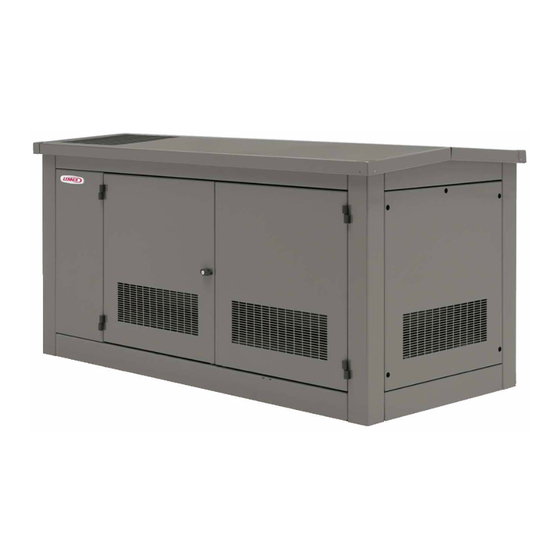
Model RGEN30 residential generator sets. Operation
manuals are available separately.
The generator set is approved for use in stationary
standby applications in locations served by a reliable
utility power source.
Have a Lennox dealer who is approved to sell and install
Lennox generator sets (hereinafter referred to as a
Lennox dealer) install the generator set outdoors
according to the instructions in this manual.
generator set installation must comply with the National
Electrical Code (NEC) and local code requirements. Do
not install this generator set indoors. If the generator set
is installed in Canada, the installation must comply with
the Canadian Electrical Code (CEC) and all applicable
local codes.
Information in this publication represents data available
at the time of print. The manufacturer reserves the right
to change this publication and the products represented
without notice and without any obligation or liability
whatsoever.
Read this manual and carefully follow all procedures
and safety precautions to ensure proper equipment
operation and to avoid bodily injury. Read and follow the
Safety Precautions and Instructions section. Keep this
manual with the equipment for future reference.
Shipping and Packing List
1 -- Generator Set
Check equipment for shipping damage. If you find any
damage, immediately contact the last carrier.
506090-01
INSTALLATION
INSTRUCTIONS
RGEN30
RESIDENTIAL GENERATOR SET
XP-6341
6/10b
Table of Contents
. . . . . . . . . . . . . . . . . . . . . . . . . . . . . . . . . . .
1.1
1.2
1.3
1.4
1.5
1.5.1
1.5.2
1.6
1.7
1.7.1
1.7.2
1.7.3
1.7.4
1.7.5
1.7.6
The
1.7.7
1.7.8
2.1
2.1.1
2.1.2
2.1.3
2.1.4
2.2
2.2.1
2.2.2
2.2.3
2.2.4
2.2.5
2.2.6
2.2.7
2.2.8
2.2.9
3.1
3.2
3.3
3.4
RETAIN THESE INSTRUCTIONS
FOR FUTURE REFERENCE
. . . . . . . . . . . . .
. . . . . . . . . . . . . . . . . . . . . . . . . . . . . .
. . . . . . . . . . . . . . . . . . . . . . . . . . . . . .
. . . . . . . . . . . . . . . . . .
. . . . . . . . . . . . .
. . . . . . . . . . . . . . . . . . . . . . . . . . . . .
. . . . . . . . . . . . . . . . . . . . . . . . . . . . .
. . . . . . . . . . . . . . . . . . . . . . . . . . . . . . .
. . . . . . . . . . . . . . . . . . . . . . . . . .
. . . . . . . . . . . . . . . . . . . . . . . . . . .
. . . . . . . . . . . . . . . . . . . . . . . . .
. . . . . . . . . . . . . . . . . . . . .
. . . . . . . . . . . . . . . . . . . .
. . . . . . . . . . . . . . . . . . .
. . . . . . . . . . .
. . . . . . . . . . . . . . . .
. . . . . . . . . . . . . . . . . . . . . . . . .
. . . . . . . . . . . . . .
. . . . . . . . . . . . . . .
. . . . . . . . . . . . . . .
. . . . . . . . . . . . . . . . . . . . . . . . . . . . . .
. . . . . . . . . . . . . . . . . . . . . . . . .
. . . . . . . . . . . . . . . . . . . . . . . .
. . . . . . . . . . . . . . . . . . . . . . . .
. . . . . . . . . . . . . . . . . . . . . .
. . . . . . . . . . . . . . . . . . . . .
. . . . . . . . . . . . . . . . . . . . . . . . . . . . .
. . . . . . . . . .
. . . . . . . . . . . . . . . .
. . . . . . . . . . . . . .
. . . . . . . . . . . .
. . . . . . . . . . . . . . .
. . . . . . . . . . . . . . . . . . . . . . . . . . . . .
. . . . . . . . . . . . .
. . . . . . . . . . . . . . . . . . . . . . . . . .
. . . . . . . . . . . . . . . . . . . . . . . . . . . .
. . . . . . . . . .
. . . . . . . . . . . . . . . . . . . . . . . . . . . .
. . . . . . . . . . . . . . . . . . .
. . . . . . . . . . . . . . . . . . . . . .
3
7
8
8
8
8
8
8
8
8
9
9
9
9
9
10
10
12
12
12
13
13
13
14
14
14
14
15
15
16
16
17
18
. .
19
. .
21
22
22
24
25
25
25
25
29
. . . .
32
Advertisement
Table of Contents

Related Manuals for Lennox RGEN30


Summary of Contents for Lennox RGEN30
-
Page 1: Table Of Contents
1.7.2 Electrical Connections ....Have a Lennox dealer who is approved to sell and install 1.7.3 Load Lead Connections .... - Page 2 California Proposition 65 WARNING Engine exhaust from this product contains chemicals known to the State of California to cause cancer, birth defects, or other reproductive harm. Product Identification Information Product identification numbers determine service parts. Controller Identification Record the product identification numbers in the spaces Record the controller description from the generator set below immediately after unpacking the products so that operation manual, spec sheet, or sales invoice.
-
Page 3: Safety Precautions And Instructions
Safety Precautions and Instructions IMPORTANT SAFETY INSTRUCTIONS. Accidental Starting WARNING Electromechanical equipment, including generator sets, transfer WARNING switches, switchgear, and accessories, can cause bodily harm and pose life-threatening danger when improperly installed, operated, or maintained. To prevent accidents be Explosion. aware of potential dangers and act Can cause severe injury or death. - Page 4 Battery short circuits. Explosion Combustible materials. A fire can Carbon monoxide symptoms. can cause severe injury or death. cause severe injury or death. Carbon monoxide can cause severe Short circuits can cause bodily injury Generator set engine fuels and fuel nausea, fainting, or death.
- Page 5 lines with rigid lines. Use flexible Hazardous Voltage/ Grounding electrical equipment. sections to avoid fuel line breakage Hazardous voltage cause Moving Parts caused by vibration. Do not operate the severe injury or death. Electrocution generator set in the presence of fuel is possible whenever electricity is leaks, fuel accumulation, or sparks.
- Page 6 Connecting the battery and the Hot Parts battery charger. Hazardous voltage can cause severe injury or death. WARNING Reconnect battery correctly, positive to positive and negative to negative, to avoid electrical shock and damage to the battery charger and battery(ies). Have qualified electrician install the battery(ies).
-
Page 7: Introduction
Literature Type Part Number Installation Manual, RGEN30 XP-6341 Operation Manual (Generator Set) XP-6344 Parts Catalog* XP-6319 Service Manual (Engine) -
Page 8: Section 1 General
The generator set and accessories must be installed by Note: Block heater damage. The block heater will fail a Lennox dealer or authorized representative. The if the energized heater element is not immersed installation must comply with all applicable national and in coolant. -
Page 9: Oil Makeup Kit
set specification sheet for fuel supply pressure 1.7.2 Electrical Connections requirements. Several electrical connections must be made between Primary gas regulator. The primary regulator reduces the generator set and other components of the system the high pressure from a tank or transmission line to the for proper operation. -
Page 10: Ground And Neutral Connections
1.7.4 Ground and Neutral Connections generator set or lifted from the ground stud and isolated if the installation requires an ungrounded neutral connection at the generator. The generator set will Ground the generator set. The grounding method must operate properly with the neutral either bonded to comply with NEC and local codes. - Page 11 Tightening Torque, Nm (in. lb.) Hexagonal Head—External Wire Size for Unit Slot Head 4.7 mm (No. 10) or Larger* Drive Socket Wrench Connection Slot Width <1.2 mm (0.047 in.) Slot Width >1.2 mm (0.047 in.) Split-Bolt Other AWG, kcmil (mm Slot Length <6.4 mm (0.25 in.) Slot Length >6.4 mm (0.25 in.) Connectors...
-
Page 12: Battery Chargers
1.7.6 Battery Chargers 1.7.8 Automatic Transfer Switches An engine-driven, battery-charging alternator charges A typical standby system has at least one automatic the battery whenever the generator set operates. transfer switch connected to the generator set output to Engine-driven systems can quickly restore the charge automatically transfer the electrical load to the used in a normal cranking cycle. -
Page 13: Section 2 Installation Instructions
Ensure you comply with all applicable codes and standards. Electrically ground the Have the generator set installed by a Lennox dealer or generator set, transfer switch, and related equipment and authorized representative. Install the equipment in electrical circuits. -
Page 14: Mounting Surface
Meet applicable fire rating codes and standards. 2.1.4 Lifting Generator Set Position the generator set over a noncombustible WARNING surface. DO NOT allow accumulation of combustible materials under or around the generator set. Permit vibration isolation to reduce noise and prevent damage. -
Page 15: Prepare Site
Installer/Customer-Supplied Items: b. Spread a 76 mm (3 in.) thick layer of gravel to support the concrete mounting pad. For the One 12-volt battery with a minimum rating of 525 cold mounting pad dimensions, see Figure 4-3 or cranking amps (CCA) at 0_F. for weather enclosures or Figure 4-4 for sound Remote harness with pigtail connector enclosures. -
Page 16: Connect Ac And Dc Wiring
Generator sets are shipped with the generator set 5. Use the remote harness with pigtail connector at neutral attached to the generator set in the junction the customer interface connector to connect box. At installation, the neutral can be grounded at engine start leads 3 and 4 to the engine start the generator set or lifted from the ground stud and terminals on the transfer switch. -
Page 17: Install And Connect Fuel Supply
6. Connect the red battery cable to the positive (+) Model Gas Flow Rate, Btu/hr. battery terminal. RGEN30 450000 7. Connect the black battery cable to the negative (--) Figure 2-2 Gas Flow Rate (natural gas and LP) battery terminal. -
Page 18: Generator Set Fuel Systems
Have your fuel supplier install a manual fuel shutoff valve and rigid gas piping. Bring the pipe to within 254 mm (10 in.) of the generator set fuel inlet location. See Figure 2-6. GM39949D--R Note: UL 2200-listed units include a second fuel valve. 1. -
Page 19: Fuel Conversion Procedures, Early Models
2.2.7 Fuel Type Check and Conversion Procedures, Early Models Note: This procedure applies to models equipped with the fuel regulator shown in Figure 2-7. For later models equipped with IEPR, Section 2.2.8. Check that the fuel system is set up for the fuel being used (natural gas or LP). - Page 20 LP Fuel Conversion Procedure Use the following steps to convert the fuel system to LP gas, if necessary: 1. Remove the fuel regulator cover plug. Figure 2-11. 2. Remove the adjustment screw and spring from the fuel regulator. Save the adjustment screw and spring for possible conversion back to natural gas.
-
Page 21: Fuel Conversion Procedures, Later Models
2.2.8 Fuel Type Check and Conversion Procedures, Later Models with IEPR Note: This procedure applies to models equipped with the integrated electronic pressure regulator and fuel valves shown in Figure 2-8. Check the connections to the fuel solenoid valve to verify that the fuel system is set up for the type of fuel that will be used (natural gas or LP). -
Page 22: Add Coolant
2.2.9 Add Coolant Follow the instructions below to fill the cooling system. 1. Close the radiator’s coolant drain valve and tighten the hose clamps. Note: Do not add coolant to a hot engine. Adding coolant to a hot engine can cause the cylinder block or cylinder head to crack. - Page 23 2. Disconnect power to battery charger, if equipped. 14. Use a digital multimeter to check the output voltage and frequency. Verify 120 volts line-to-neutral and 3. Disconnect the generator set engine starting 60 Hz output. battery, negative (--) lead first. 15.
-
Page 24: Operation Tests
18. Disconnect the load. 1. Verify that all guards are in place. Install the enclosure’s end panels and nonservice side door. 19. Adjust the idle screw (see Figure 2-16) to obtain a no-load oxygen sensor voltage reading of 2. Check the items in the Prestart Checklist in the 2.5 ±0.10 VDC (or a lambda λ... -
Page 25: Section 3 Controller
ADC 2100 application code version 3.25 or later. The code version is displayed as you enter the controller Have controller setup and adjustment performed only by configuration mode. See Figure 3-2. a Lennox dealer or authorized representative. 3.3 Controller Configuration 3.1 Controller Automatic Power Down... - Page 26 Note: This parameter sets the nominal system voltage user to set the controller for communication with and frequency. To adjust the output (measured) optional meters. The RGEN30 is factory-set for no CAN voltage, see Section 3.4. communications, Cn00. Change this setting to Cn01 or Cn06 if an optional Remote Digital Gauge is used.
- Page 27 Controller Configuration Mode: Hold the Select button: Display: Move the generator set master switch to the RUN position. (The generator set engine will not start.) Wait about 5 seconds until the display shows 1 0 4 the program version number. (The number may be different than the one shown here.) Press the down arrow key and then the up arrow key 3 times to enter the configuration...
- Page 28 Pressing the up arrow key at the Adnc display (See Figure 3-2) puts you into the Advanced Configuration Mode. Press: E d 0 1 To set the engine data input type to Ed01. See Figure 3-1. To enter battery voltage selection mode. To toggle between 12 and 24 VDC.
-
Page 29: Voltage Adjustments
1P. See Figure 3-6 The controller’s adjustment mode allows adjustment of for adjustment instructions. the output voltage, if necessary. Have adjustments performed by a Lennox dealer or service technician. Voltage Change per Step, VAC Measured Voltage, VAC... - Page 30 Output Voltage Adjustment Mode: Display :* x x x x Move the generator set master switch to the RUN position. The generator set engine starts and the controller display shows the engine runtime hours. Hold: Wait about 5 seconds until the display changes from runtime hours to the program version number.
- Page 31 Display : * Continued from Figure 3-6: To enter SAVE mode. S A V E Note: Be sure to save your settings before exiting the configuration mode. The controller reverts to the last saved settings when the master switch is moved to the OFF/RESET position. There are 3 options when the display says SAVE: S A V E Press:...
-
Page 32: Section 4 Diagrams And Dimension Drawings
Section 4 Diagrams and Dimension Drawings Later model generator sets use an updated fuel system. Fuel System Generator Set Drawing Version See Section 2.2.6 and compare your generator set’s fuel Illustration Serial Number Number system to Figure 2-7 and Figure 2-8 to determine which Figure 2-7 Below 2272938 fuel system is installed, or check the generator set serial... - Page 33 Figure 4-3 Generator Set Dimensions (shown without enclosure), ADV-7000A-D XP-6341 6/10 Section 4 Diagrams and Dimension Drawings...
- Page 34 Figure 4-4 Sound Enclosure Dimensions, ADV-7000C-D Section 4 Diagrams and Dimension Drawings XP-6341 6/10...
- Page 35 Figure 4-5 Installation Clearance Drawing, ADV-7000D-D XP-6341 6/10 Section 4 Diagrams and Dimension Drawings...
- Page 36 Figure 4-6 High Wind Mounting Pad Detail Drawing, ADV-7000E-D Section 4 Diagrams and Dimension Drawings XP-6341 6/10...
- Page 37 Figure 4-7 GM 1.6 L Schematic Diagram, Page 1, ADV-7287A-A XP-6341 6/10 Section 4 Diagrams and Dimension Drawings...
- Page 38 Figure 4-8 Schematic Diagram, Page 2, ADV-7287B-A Section 4 Diagrams and Dimension Drawings XP-6341 6/10...
- Page 39 Figure 4-9 Wiring Diagram, Page 1, GM50548A-C XP-6341 6/10 Section 4 Diagrams and Dimension Drawings...
- Page 40 Figure 4-10 Wiring Diagram, Page 2, GM50548B-C Section 4 Diagrams and Dimension Drawings XP-6341 6/10...
- Page 41 Figure 4-11 Generator Set Dimensions (shown without enclosure), ADV-7692A-A, Sheet 1 XP-6341 6/10 Section 4 Diagrams and Dimension Drawings...
- Page 42 Figure 4-12 Generator Set Dimensions (shown without enclosure), ADV-7692B-A, Sheet 2 Section 4 Diagrams and Dimension Drawings XP-6341 6/10...
- Page 43 Figure 4-13 ADV-7694B-B, Sound Enclosure XP-6341 6/10 Section 4 Diagrams and Dimension Drawings...
- Page 44 Figure 4-14 Installation Clearance Drawing, ADV-7694C-B Section 4 Diagrams and Dimension Drawings XP-6341 6/10...
- Page 45 Figure 4-15 Schematic Diagram, ADV-7602A-B, Sheet 1 XP-6341 6/10 Section 4 Diagrams and Dimension Drawings...
- Page 46 Figure 4-16 Schematic Diagram, ADV-7602B-B, Sheet 2 Section 4 Diagrams and Dimension Drawings XP-6341 6/10...
- Page 47 Figure 4-17 Schematic Diagram, ADV-7602C-B, Sheet 3 XP-6341 6/10 Section 4 Diagrams and Dimension Drawings...
- Page 48 Figure 4-18 Wiring Diagram, GM63943A-A Sheet 1 Section 4 Diagrams and Dimension Drawings XP-6341 6/10...
- Page 49 Figure 4-19 Wiring Diagram, GM63943B-A Sheet 2 XP-6341 6/10 Section 4 Diagrams and Dimension Drawings...
- Page 50 Notes Section 4 Diagrams and Dimension Drawings XP-6341 6/10...
- Page 51 Notes XP-6341 6/10 Section 4 Diagrams and Dimension Drawings...
- Page 52 Notes Section 4 Diagrams and Dimension Drawings XP-6341 6/10...
Need help?
Do you have a question about the RGEN30 and is the answer not in the manual?
Questions and answers