Table of Contents
Advertisement
©2004 Lennox Industries Inc.
Dallas, Texas
HSXA19 Outdoor Unit
Two−stage HSXA19 outdoor units use R410A which is an
ozone friendly HFC refrigerant. This unit must be installed
with a matching indoor coil and line set as outlined in the
Lennox Engineering Handbook. Dave Lennox Signaturet
Collection HSXA19 outdoor units are designed for use in ex-
pansion valve systems (TXV) only. They are not designed to
be used with other refrigerant flow control devices. The Len-
nox Engineering Handbook lists a TXV kit that must be or-
dered separately.
Shipping & Packing List
1 − Assembled HSXA19 outdoor unit
2 − Grommets (liquid and vapor line)
1 − Bushing (for low voltage wiring)
Check equipment for shipping damage. If you find any
damage, immediately contact the last carrier.
CAUTION
Danger of sharp metallic edges. Can cause injury.
Take care when servicing unit to avoid accidental
contact with sharp edges.
WARNING
Improper installation, adjustment, alteration, service
or maintenance can cause property damage, person-
al injury or loss of life. Installation and service must
be performed by a qualified installer or service
agency.
IMPORTANT
This unit must be matched with an indoor coil as
specified in Lennox' Engineering Handbook. Coils
previously charged with HCFC−22 must be flushed.
04/04
*2P0404*
INSTALLATION
INSTRUCTIONS
HSXA19 SERIES UNITS
CONDENSING UNITS
504,919M
04/04
Supersedes 03/04
Table of Contents
. . . . . . . . . . . . . . . . . . . . . . . . . . . . . . .
. . . . . . . . . . . . . . . . . . . . . . . . . . . . . . . .
. . . . . . . . . . . . . . . . . . . . . . . . . . . . . . . . . . . . . .
. . . . . . . . . . . . . . . . . . . . . . . . . . . . . . . .
. . . . . . . . . . . . . . . . . . . . . . . . . . . . . . . . . .
. . . . . . . . . . . . . . . . . . . . . . . . . . . . . . . . . . .
. . . . . . . . . . . . . . . . . . . . . . . . . . . . . . . . . . . . . .
. . . . . . . . . . . . . . . . . . . . . . . . . . . . . . . . . . . . .
. . . . . . . . . . . . . . . . . . . . . . . . . . . . . . . . . .
. . . . . . . . . . . . . . . . . . . . . . . . . . . . . . . . .
Retain These Instructions
For Future Reference
General Information
These instructions are intended as a general guide and do
not supersede local codes in any way. Consult authorities
who have jurisdiction before installation.
This product and/or the indoor unit it is matched with
may contain fiberglass wool.
Disturbing the insulation during installation, mainte-
nance, or repair will expose you to fiberglass wool
dust. Breathing this may cause lung cancer. (Fiber-
glass wool is known to the State of California to
cause cancer.)
Fiberglass wool may also cause respiratory, skin,
and eye irritation.
To reduce exposure to this substance or for further
information, consult material safety data sheets
available from address shown below, or contact your
supervisor.
Lennox Industries Inc.
P.O. Box 799900
Dallas, TX 75379−9900
Page 1
. . . . . . . . . . . . . . . . . . . . . . . . . .
. . . . . . . . . . . . . . . . . . . . . . . . .
. . . . . . . . . . . . . . . . . . . . . . . . . . . .
. . . . . . . . . . . . . . . . . . . . . . . . . . . . .
. . . . . . . . . . . . . . . . . . . . . . . . . . . . . .
. . . . . . . . . . . . . . . . . . . .
. . . . . . . . . .
. . . . . . . . . . . . . . . . . . . . . . . . . . .
. . . . . . . . . . . . . . . . . . . . . . . . . . . . .
. . . . . . . . . . . . . . . . . . . . . . . . . .
. . . . . . . . . . . . . . . . . . . . . . . .
WARNING
504,919M
*P504919M*
Litho U.S.A.
1
1
1
2
3
3
4
7
11
11
13
14
15
15
16
16
21
23
23
23
24
Advertisement
Table of Contents

Related Manuals for Lennox HSXA19 SERIES


Summary of Contents for Lennox HSXA19 SERIES
-
Page 1: Table Of Contents
........Lennox Engineering Handbook. Dave Lennox Signaturet Evacuation . -
Page 2: Unit Dimensions
Unit Dimensions – Inches (mm) INLET INLET COMPRESSOR INLET TOP VIEW ELECTRICAL 32-1/8 (816) INLETS 34-1/16 (865) DISCHARGE SUCTION LINE INLET 4-1/2 (114) LIQUID LINE INLET 2-9/16 (65) 9-1/8 9-1/8 (232) (232) 3-1/8 3-1/8 3-1/8 18-5/8 2-3/4 (70) (79) (79) (79) (473) (102) -
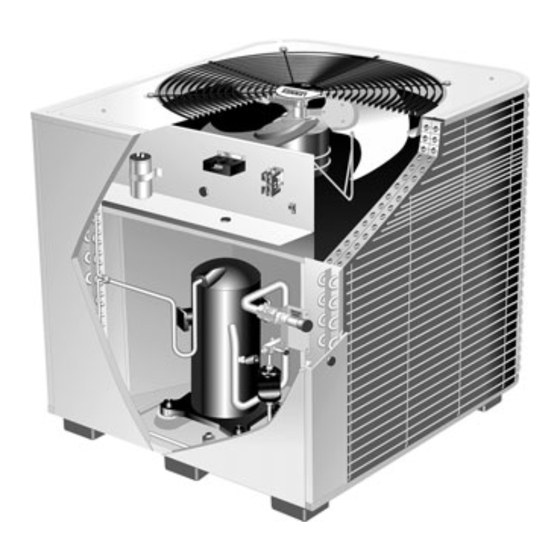
Page 3: Parts Arrangement
Parts Arrangement system operation monitor outdoor fan run capacitor (variable speed on HSXA19−038) start capacitor (HSXA19−024) discharge line contactor compressor terminal plug vapor valve and two−stage compressor gauge port filter drier vapor line high pressure switch low pressure switch Figure 1 A −... -
Page 4: Electrical
B − Roof Mounting WARNING Install unit at a minimum of 4 inches above surface of the roof. Care must be taken to ensure weight of unit is properly Unit must be grounded in accordance with national and local codes. Electric Shock Hazard. Can cause distributed over roof joists and rafters. - Page 5 HSXA19−024, −036, −048, and −060 Wiring Diagram Figure 5 Page 5...
- Page 6 HSXA19−038 Wiring Diagram Figure 6 Page 6...
-
Page 7: Refrigerant Piping
(sweat connections) to the indoor coil important to properly isolate the refrigerant lines to prevent (flare or sweat connections). Use Lennox L15 (sweat, non- unnecessary vibration. Line set contact with the structure flare) series line sets as shown in table 1 or use field-fabri- (wall, ceiling or floor) causes some objectionable noise cated refrigerant lines. - Page 8 Refrigerant Line Sets How To Install Vertical Runs (new construction shown) NOTE - Similar installation practices should be used if line set is to be installed on exterior of outside wall. IMPORTANT - Refrigerant Outside Wall Vapor Line Liquid Line lines must not contact wall.
- Page 9 Refrigerant Line Sets: Installing Horizontal Runs To hang line set from joist or rafter, use either metal strapping material Wire Tie or anchored heavy nylon wire ties. (around vapor line only) 8 feet Floor Joist or Roof Rafter Tape or Wire Tie 8 feet Strapping Material (around vapor line only) Metal Sleeve...
- Page 10 Refrigerant Line Sets: Transition From Vertical To Horizontal Automotive Anchored Heavy Muffler-Type Nylon Wire Tie Hanger Wall Wall Stud Stud Strap Liquid Line Strap Liquid Line To Vapor Line To Vapor Line Liquid Line Vapor Line Metal Vapor Line Wrapped in Metal Sleeve Liquid Line...
-
Page 11: Refrigerant Metering Device
R410A refrigerant) in the liquid line to installation. Take care to empty all existing traps. at the indoor coil. Polyol ester (POE) oils are used in Lennox units charged with R410A refrigerant. Residual mineral Refrigerant Metering Device oil can act as an insulator, preventing proper heat transfer. - Page 12 close the liquid line valve. Pump all of the existing CAUTION HCFC−22 refrigerant back into the outdoor unit. (It may be necessary to bypass the low pressure switches to This procedure should not be performed on sys- ensure complete refrigerant evacuation.) When the tems which contain contaminants (Example: com- pressor burn out).
-
Page 13: Manifold Gauge Set
Flushing Connections Inverted HCFC−22 Cylinder (Contains clean HCFC−22 to be used for flushing) HIGH PRESSURE PRESSURE HSXA19 UNIT VAPOR LINE SERVICE VALVE EXISTING VAPOR LINE Existing GAUGE MANIFOLD Indoor Coil OPENED CLOSED EXISTING LIQUID LINE LIQUID LINE SERVICE VALVE TANK RETURN NOTE −... -
Page 14: Service Valves
Service Valves Liquid Line Service Valve (Valve Closed) The liquid line and vapor line service valves (figure 13) and service service port and gauge ports are used for leak testing, evacuating, port cap charging and checking charge. See table 2 for torque re- quirements. -
Page 15: Leak Testing
6 − After a few minutes, open a refrigerant port to check Leak Testing that an adequate amount of refrigerant has been add- After the line set has been connected to the indoor and ed for detection (refrigerant requirements will vary outdoor units, check the line set connections and indoor with line lengths). -
Page 16: Start−Up
der with pressure regulator set to 150 psig (1034 kPa) 7 − Recheck voltage while the unit is running. Power must and purge the hose. Open the manifold gauge valves be within range shown on the nameplate. to break the vacuum in the line set and indoor unit. Charging Close the manifold gauge valves. - Page 17 Connect the center manifold hose to an upright cylin- Blocking Outdoor Coil der of R410A. Close manifold gauge set valves. *Outdoor coil should be 2 − Set the room thermostat to call for heat. This will create blocked one side the necessary load for properly charging the system in at a time with cardboard or plastic sheet until proper...
- Page 18 Charging Using Normal Operating Pressures atures should match values given in table 5. If the val- ues don’t agree with the those in table 5, add refriger- and the Approach Method ant to lower the approach temperature, or recover re- Outdoor Temp.
- Page 19 Table 6 Normal Operating Pressure (Liquid ±10 and Vapor ±5 psig) First Stage (Low Capacity) Outdoor Coil Entering −024 −036 −038 −048 −060 Air Temp. °F (°C) Air Temp. F ( C) Liquid Vapor Liquid Vapor Liquid Vapor Liquid Vapor Liquid Vapor 65 (18.3)
- Page 20 Table 7 R410A Temperature/Pressure Chart Temperature Pressure Temperature Pressure Temperature Pressure Temperature Pressure °F Psig °F Psig °F Psig °F Psig 100.8 178.5 290.8 445.9 102.9 181.6 295.1 451.8 105.0 184.3 299.4 457.6 107.1 187.7 303.8 463.5 109.2 190.9 308.2 469.5 111.4 194.1...
-
Page 21: System Operation
System Operation System Operation Monitor The outdoor unit and indoor blower cycle on demand from the room thermostat. When the thermostat blower switch is in the ON position, the indoor blower operates continuously. Two−Stage Compressor The two stage scroll compressor operates much like the standard scroll compressor with the exception the two step compressor steps between low capacity and full capacity. - Page 22 A drier is factory−installed in each HSXA19 unit. A replace- HSXA19 units are also equipped with a low pressure switch ment drier is available from Lennox. See the Lennox Engi- that is located in the vapor line of the compressor. The neering Handbook.
-
Page 23: Maintenance
NOTE − It may be necessary to flush the outdoor Ask your Lennox dealer to show you where your indoor coil more frequently if it is exposed to substances unit’s filter is located. It will be either at the indoor unit... -
Page 24: Check Points
Leaves, trash or shrubs crowding the Programmable Thermostats unit cause the outdoor unit to work harder and use more Your Lennox system may be controlled by a energy. Keep shrubbery trimmed away from the unit and programmable thermostat. These thermostats provide...
Need help?
Do you have a question about the HSXA19 SERIES and is the answer not in the manual?
Questions and answers