Table of Contents
Advertisement
control – motion –
for Incremental Encoder Signals
Power supply
10 – 30 VDC
Cascading input
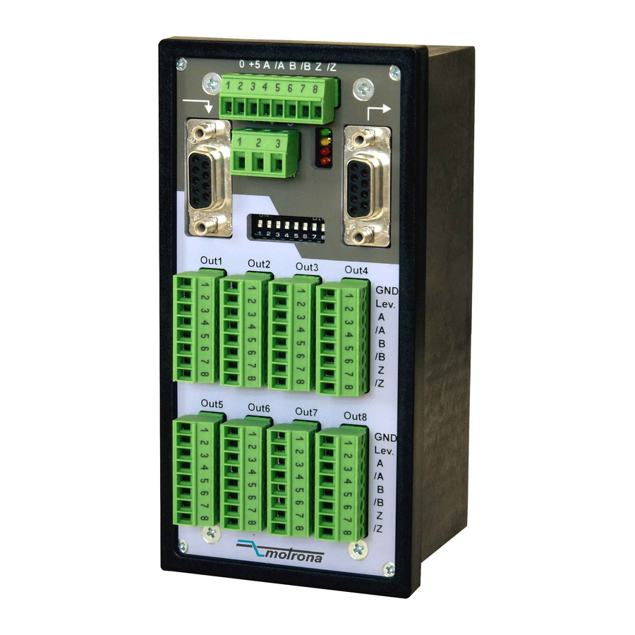
8 output channels, each
A, /A, B, /B, Z, /Z,
potential-separated
from input, each with
individual output level
GV47001b_e.doc / Feb-08
interface
GV 470
Universal 8-Channel Splitter
Operating Instructions
ELEKTRO-TRADING sp. z o.o
Tel.
+48 (0-32) 734-55-72
Tel/Fax +48 (0-32) 734-55-70
E-Mail et@elektro-trading.com.pl
http://www.elektro-trading.com.pl
Universal
Encoder input
RS422 or HTL (10-30V)
LEDs for display of
input channels A, B, Z
Cascading output
Page 1 / 9
Advertisement
Table of Contents

Subscribe to Our Youtube Channel
Related Manuals for Motrona GV 470


Summary of Contents for Motrona GV 470
- Page 1 ELEKTRO-TRADING sp. z o.o Tel. +48 (0-32) 734-55-72 Tel/Fax +48 (0-32) 734-55-70 E-Mail et@elektro-trading.com.pl http://www.elektro-trading.com.pl control – motion – interface GV 470 Universal 8-Channel Splitter for Incremental Encoder Signals Universal Encoder input RS422 or HTL (10-30V) Power supply LEDs for display of 10 –...
- Page 2 Safety Instructions • This manual is an essential part of the unit and contains important hints about function, correct handling and commissioning. Non-observance can result in damage to the unit or the machine, or even in injury to persons using the equipment ! •...
-
Page 3: Table Of Contents
Table of Contents 1. Introduction and Block Diagram..............4 2. Electrical Connections and LEDs..............5 2.1. Power Supply and LED Assignment............... 5 2.2. Encoder Input......................5 2.3. Outputs........................6 2.4. Cascading of Several Units and Encoder Select Function ........6 3. -
Page 4: Introduction And Block Diagram
Furthermore, cascaded configurations allow remote selection and switch-over between several input encoders. GV 470 is built into a most compact and space-saving housing for mounting on DIN rails. The following drawing explains the principle of function with one of the eight output channels:... -
Page 5: Electrical Connections And Leds
2. Electrical Connections and LEDs 2.1. Power Supply and LED Assignment The unit provides a 3-position screw terminal strip for supply from a 10 – 30 volts DC power unit. The current consumption is approx. 100 mA (no-load operation). The “Select” input terminal provides selection of the desired source encoder. Details will be described later. -
Page 6: Outputs
1, 3, 5 and 7 of the cascading output must be connected to the corresponding pins of the cascading input of the follower unit. An appropriate ribbon cable connection is available under motrona part # FK470 FK470 GV47001b_e.doc / Feb-08... - Page 7 Cascaded units allow selection of the active source encoder via the encoder select input on the 3-position power connector (see also block diagram): LOW (or open): outputs refer to the encoder input of the same unit HIGH (10 – 30 volts): outputs refer to the encoder input of the preceding unit It is possible at any time to switch over from one to the other source encoder during operation, therefore cascaded units can also operate as a cross-switch.
-
Page 8: Input Settings By Dil Switch
3. Input Settings by DIL Switch Positions 1 – 6 of the DIL switch serve to set the desired input levels. This setting can be done for each of the input terminals individually. Switch # Input line OFF: Associated input line requires HTL level (10 – 30 volts) Associated input line requires RS422 characteristics (2 –... -
Page 9: Technical Specifications And Dimensions
4. Technical Specifications and Dimensions Power supply: 10 – 30 Vdc Power consumption: approx. 100 mA, plus currents taken from the (without aux. encoder supply) output lines Maximum frequency: RS422: 500 kHz, HTL: 200 kHz Input level with RS422 operation: 2,0 –...
Need help?
Do you have a question about the GV 470 and is the answer not in the manual?
Questions and answers