Lutron Electronics Roller 100 Installation Manual
Fascia mount chassis
Hide thumbs
Also See for Roller 100:
- Installation instructions manual (24 pages) ,
- Installation instructions manual (24 pages)
Advertisement
Quick Links
Lutron
roller 100
/
English
™
®
roller 150
fascia
™
mount chassis
Installation Guide (please read before installing)
The roller 100/roller 150 Fascia Mount Chassis Installation Guide
is a complement to the enclosed Basic Wiring and Setup Guide.
The Chassis Installation Guide describes the mechanical
installation. The Basic Wiring and Setup Guide describes the
wiring and setup for proper function of the roller shade.
Tools required:
• Tape Measure
• Power Drill
• #2 Phillips Screwdriver
• 1/4 in Hex-Head Driver
• Level
Box Contents:
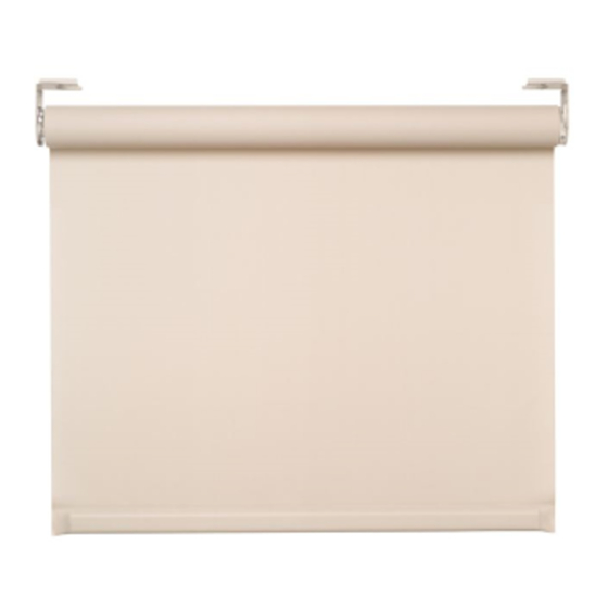
(1) Lutron roller 100/ roller 150 shade
(1) Fascia
(1) Top/back cover
(2) Fascia end caps
(1) Left and (1) right
(8) Mounting screws
fascia sub-bracket
(#8x1-3/4 in)
CAUTION:
!
Risk of minor or moderate injury from falling heavy objects
Securely install the roller shade per the mounting instructions.
Notes:
Lutron systems are intended for use with only Lutron hardware, controls,
•
and power supplies.
•
Codes: Install in accordance with all local and national electrical codes.
Environment: Ambient operating temperature: 32 °F - 104 °F
•
(0 °C - 40 °C), 0 - 90% humidity, non-condensing. Indoor use only.
Maintain sufficient clearance between the moving shade and any object.
•
1
Pre-drill the top/back cover for cable run
Note: This step is not necessary if the top/back cover is not being used.
1.1
Determine where to drill for cable access.
See options below. Cable should exit from
wall, ceiling or jamb on the Drive side of
fascia.
NOTES:
Leave 12 to 18 in (305 to 457 mm) of
•
cable exposed.
Cable should exit from one of these
•
locations whether the top/back cover
is used or not.
Wall
Drill for the cable in the location indicated
by the label on top/back cover.
Ceiling
Drill for the cable in the location indicated
by the label on top/back cover.
Jamb
Drill for the cable 2 in (51 mm) from
the top and 2 in (51 mm) from the back
of the top/back cover.
2 in
(51 mm)
2 in
(51 mm)
2
Mount top/back cover
2.1
Verify the mounting surface is
Acceptable
level/plumb before attaching the
top/back cover. Shim if necessary.
NOTE: Top/back cover
may rub fabric if installed
with excessive tilt.
Recommended
2.2
Mount the top/back cover using the
appropriate fasteners. It may
be necessary to pre-drill clearance
holes in the Top/Back cover before
mounting.
Unacceptable
Screws must be at least
5 in (127 mm) from the end of
the fascia to avoid interference
with the sub-brackets.
3
Mount fascia sub-brackets
3.1
Use the alignment holes to position
Top/back cover width
the sub-bracket right to left.
The alignment holes will line
up with the outside edge of
the shade tube.
Fabric Width
.75 in
(19 mm)
System Width
3.2
If endcaps are being used,
they must be installed
snapped into the sub-brack-
ets. Insert the sub-brackets
by rotating into place as
shown below.
Align
With Edge
Of Tube
CAUTION:
Risk of minor
!
or moderate injury from
falling heavy objects.
Securely attach the
sub-bracket to a structural
member.
3.3
Mount the sub-brackets
using appropriate fasteners.
4
Mount the shade to sub-brackets
NOTICE: Shades wider than 4 ft (1.2 m) require two people to install.
4.1
Remove the retaining screws from
the shade brackets.
NOTE: Leave the protective wrapping
on shade during installation.
4.2
Hook the tongue of each
shade bracket onto the top
of each sub-bracket.
4.3
Rotate the shade up until the
front of the shade brackets
engage with the sub-brackets.
4.4
Route the cable from the wall,
ceiling or jamb between
the shade bracket and the
sub-bracket. Do not pinch
the cable.
5
Center and secure shade
5.1
Move the shade left
or right until centered
on the window.
5.2
Insert and tighten the
retaining screws on
BOTH shade brackets
.75 in
(19 mm)
to secure the shade
into position. Screws
must be fully tightened.
Verify the retaining screw
is going into the slot in the
sub-bracket.
CAUTION:
Risk of minor
!
or moderate injury from
falling heavy object.
Ensure the shade bracket
is securely attached to the
sub-bracket.
6
Leveling the shade
6.1
Turn the leveling screw
to raise or lower the
idler side of the shade
until level.
leveling screw
Advertisement

Subscribe to Our Youtube Channel
Related Manuals for Lutron Electronics Roller 100

Summary of Contents for Lutron Electronics Roller 100
- Page 1 Securely attach the Ensure the shade bracket The roller 100/roller 150 Fascia Mount Chassis Installation Guide Ceiling sub-bracket to a structural is securely attached to the is a complement to the enclosed Basic Wiring and Setup Guide.
- Page 2 Technical Support: 800.120.4491 WARRANTIES ARE LIMITED TO ONE YEAR FROM THE DATE OF SHIPMENT AS TO THE EXTERNAL SIVOIA ©2010 LUTRON Electronics Co., Inc. QS COMPONENTS. NO LUTRON AGENT, EMPLOYEE P/N 045-188 REV B 12/2012 OR REPRESENTATIVE HAS ANY AUTHORITY TO BIND LUTRON TO ANY AFFIRMATION, REPRESENTATION OR WARRANTY CONCERNING THE SYSTEMS.
Need help?
Do you have a question about the Roller 100 and is the answer not in the manual?
Questions and answers