Sign In
Upload
Download
Table of Contents
Contents
Add to my manuals
Delete from my manuals
Share
URL of this page:
HTML Link:
Bookmark this page
Add
Manual will be automatically added to "My Manuals"
Print this page
×
Bookmark added
×
Added to my manuals
Manuals
Brands
Garmin Manuals
Receiver
GDL 52
Installation manual
Garmin GDL 52 Installation Manual
Data link
Hide thumbs
Also See for GDL 52
:
User manual
(31 pages)
1
2
3
4
5
6
Table Of Contents
7
8
9
10
11
12
13
14
15
16
17
18
19
20
21
22
23
24
25
26
27
28
29
30
31
32
33
34
35
36
37
38
39
40
41
page
of
41
Go
/
41
Contents
Table of Contents
Bookmarks
Table of Contents
Table of Contents
Section 1 General Description
Introduction
Equipment Description
Technical Specifications
Reference Documents
Introduction
Installation Materials
Available Accessories
Section 2 Installation Overview
Installation Considerations
GDL 5X/5XR Installation Guidance for Best Wireless Performance
Cabling and Wiring
Cooling Air
Configuration, and Adjustment Options
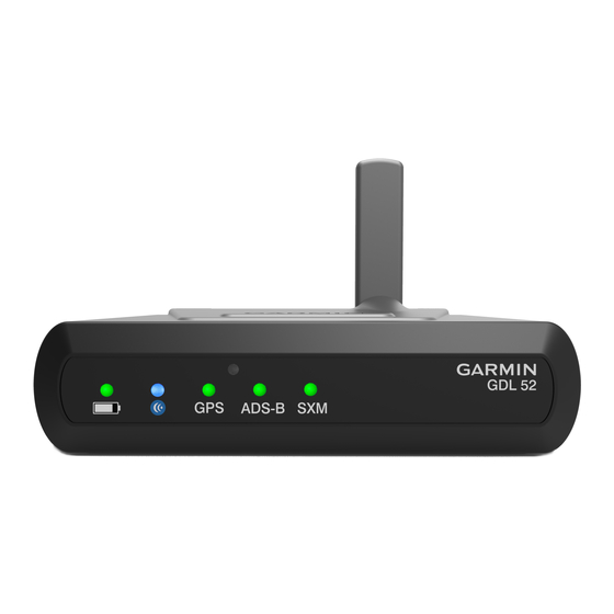
Front Panel
Updating Software
Noise
Mounting Requirements
Section 3 Installation Procedure
Unpacking Unit
Wiring Harness Installation
Backshell Assembly
Coax Cable Installation
Equipment Mounting
Continued Airworthiness
Antenna Installation
Non-Garmin Antennas
Garmin Antennas
Post Installation Checkout
Section 4 System Interconnects
Pin Function List
Appendix A Outline and Installation Drawings
Appendix B Interconnect Drawings
Advertisement
Quick Links
1
Equipment Description
2
Installation Materials
3
Installation Considerations
4
Gdl 5X/5Xr Installation Guidance for Best Wireless Performance
5
Cabling and Wiring
6
Configuration, and Adjustment Options
Download this manual
See also:
User Manual
GDL 50(R)/51(R)/52(R)
Data Link
Installation Manual
190-02087-10
August, 2018
Revision 2
Table of
Contents
Previous
Page
Next
Page
1
2
3
4
5
Advertisement
Table of Contents
Need help?
Do you have a question about the GDL 52 and is the answer not in the manual?
Ask a question
Questions and answers
Related Manuals for Garmin GDL 52
Receiver Garmin GDL 51 User Manual
Portable siriusxm, gps receiver, and ads-b receiver (31 pages)
Receiver Garmin 190-00336-00 Owner's Manual
Garmin marine weather/audio satellite receiver owner's manual (34 pages)
Receiver Garmin GDL 30A Owner's Manual
Owner's manual (34 pages)
Receiver Garmin GDL 69/69A Installation Manual
Xm satellite radio data link receiver (70 pages)
Receiver Garmin GRT 10 Transceiver Instructions Manual
Xm satellite radio activation instructions (44 pages)
Receiver Garmin GDL 69 Manual
(15 pages)
Receiver Garmin GDL 50R Installation Manual
Data link (41 pages)
Receiver Garmin GDL 51R Installation Manual
Data link (41 pages)
Receiver Garmin GDL 69AH Operator's Manual
Xm wx satellite weather/radio receiver (46 pages)
Receiver Garmin GTM 25 Instruction Manual
Real-time traffic receiver (60 pages)
Receiver Garmin GTM 10 Owner's Manual
Traffic receiver (8 pages)
Receiver Garmin 23 Owner's Manual And Reference Manual
Beacon receiver (24 pages)
Receiver Garmin GTM 11 Owner's Manual
Fm tmc traffic receiver (9 pages)
Receiver Garmin GTM 20 Instructions Manual
Traffic receiver (16 pages)
Receiver Garmin GTM 11 Owner's Manual
Fm tmc traffic receiver (68 pages)
Receiver Garmin GTM 30 Series Instructions Manual
Traffic receiver (53 pages)
This manual is also suitable for:
Gdl 51
Gdl 50r
Gdl 50
Gdl 51r
Gdl 52r
Table of Contents
Save PDF
Print
Rename the bookmark
Delete bookmark?
Delete from my manuals?
Login
Sign In
OR
Sign in with Facebook
Sign in with Google
Upload manual
Upload from disk
Upload from URL


Need help?
Do you have a question about the GDL 52 and is the answer not in the manual?
Questions and answers