Makita JR3070CT Technical Information
Recipro saw
Hide thumbs
Also See for JR3070CT:
- Instruction manual (40 pages) ,
- Parts breakdown (3 pages) ,
- Instruction manual (25 pages)
Advertisement
Quick Links
Download this manual
See also:
Instruction Manual
T
ECHNICAL INFORMATION
Models No.
Description
C
ONCEPT AND MAIN APPLICATIONS
Model JR3070CT has been developed as the highest specification
model in Makita Recipro Saws.
Features electronic control and orbital mechanism for extra-high
cutting efficiency while ensuring low vibration performance with
our innovative AVT (Anti-Vibration Technology).
Additionally, provides more control and comfort with toolless
blade change, toolless shoe adjustment and rubberized soft grip.
S
pecification
Voltage (V)
110
120
220
230
240
Stroke per minute: min-
Length of Stroke: mm (")
*Wood: mm (")
Capacity
Pipe: dia. mm (")
Variable speed control
Net weight: kg (lbs)
Power supply cord: m (ft)
*when cutting with the supplied 300mm (11-3/4") length recipro saw blade.
S
tandard equipment
North America:
Recipro saw blade (for Steel)
Recipro saw blade (for Composite)
Steel carrying case
Note: The standard equipment for the tool shown above may differ by country.
O
ptional accessories
Recipro saw blades No.21, 22, 24 (for Steel)
Recipro saw blade No.23, 23B (for Wood and Plywood)
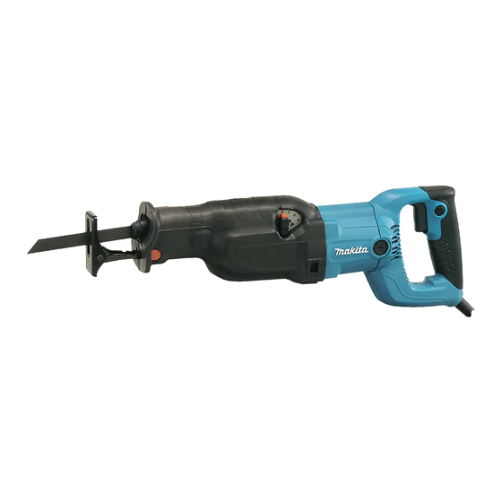
JR3070CT
Recipro Saw
Cycle (Hz)
Current (A)
14.5
50/60
15
50/60
7.2
50/60
6.9
50/60
6.6
50/60
1
All countries other than North America:
Recipro saw blades No.21 (for Steel)
Recipro saw blades No.22 (for Steel)
Recipro saw blade No.23 (for Wood and Plywood)
Plastic carrying case
H
Continuous Rating (W)
Input
1,510
1,700
1,510
1,510
1,510
0 - 2,800
32 (1-1/4)
255 (10)
130 (5-1/8)
Yes
4.4 (9.7)
Europe: 4.0 (13.1)
Australia: 2.0 (6.6)
Other countries: 2.5 (8.2)
PRODUCT
L
W
Dimensions: mm (")
Length (L)
485 (19-1/8)
Width (W)
99 (3-7/8)
Height (H)
181 (7-1/8)
Max. Output(W)
Output
650
1,600
950
1,600
650
1,600
650
1,600
650
1,600
P 1 / 15
Advertisement

Related Manuals for Makita JR3070CT


Summary of Contents for Makita JR3070CT
- Page 1 JR3070CT Description Recipro Saw ONCEPT AND MAIN APPLICATIONS Model JR3070CT has been developed as the highest specification model in Makita Recipro Saws. Features electronic control and orbital mechanism for extra-high cutting efficiency while ensuring low vibration performance with our innovative AVT (Anti-Vibration Technology).
-
Page 2: Necessary Repairing Tools
Tightening torx socket head screw M5x14 [2] LUBRICATION AND ADHESIVE APPLICATION [2] -1. LUBRICATION Blade Clamp Section Apply Makita grease FA No.2 to the following portions designated with the black triangle to protect parts and product from unusual abrasion. Item No. Description... - Page 3 P 3 / 15 epair [2] -1. LUBRICATION (cont.) Gear and Reciprocation Mechanisms Apply Makita grease FA No.2 to the following portions designated with the black triangle to protect parts and product from unusual abrasion. Item No. Description Portion to lubricate Slider support Inside surface where Slider reciprocates.
-
Page 4: Adhesive Application
P 4 / 15 epair [2] -2. ADHESIVE APPLICATION Apply adhesive to the following screws to prevent them from loosening. Item No. Description Apply for Pan head screw M5x16 (4 pcs) Securing Gear housing cover (15) (29) (42) Hex socket head bolt M5x16 (4 pcs) Tightening Plate A and B Securing Shoe guide Countersunk head screw M6x16 (1 pc) - Page 5 P 5 / 15 epair [3] DISASSEMBLY/ASSEMBLY [3] -1. Disassembling/ Assembling Blade Clamp Section Fig. 4 DISASSEMBLING Blade clamp section 1) Remove shoe. If the blade clamp section is positioned inside gear housing, pull it out of gear housing. (Fig. 4) 2) After removing protector, remove retaining ring S-18 with Retaining Ring S and R Pliers (No.1R291).
- Page 6 P 6 / 15 epair [3] -1. Disassembling/ Assembling Blade Clamp Section (cont.) ASSEMBLING 1) Assemble torsion spring 17 to slider as illustrated in Fig. 9. Important: Be sure that torsion spring 17 is not reversible when assemble to slider. Follow the instruction described in Fig.
- Page 7 P 7 /15 epair [3] -1. Disassembling/ Assembling Blade Clamp Section (cont.) 5) While fitting the two projections of driving sleeve in the concavities of sleeve, push driving sleeve into gear housing. At this time, turn driving sleeve clockwise so that the protruding portion of driving sleeve cannot be interfered by gear housing.
- Page 8 P 8/ 15 epair [3] -3. Disassembling/ Assembling Slider DISASSEMBLING 1) After removing shoe and insulation cover, remove the blade clamp section. (Refer to [3]-1.) 2) Separate gear housing cover from gear housing by removing four M5x16 pan head screws (adhesive). (Fig. 15) 3) Remove stop ring E-6, and then take off lever 20 from gear housing cover.
- Page 9 P 9/ 15 epair [3] -3. Disassembling/ Assembling Slider DISASSEMBLING 7) While raising the end of bearing complete side, remove slider from slider support by pulling in the direction of the arrow. (Fig. 19) 8) Remove X ring 14 from slider support. (Fig. 19) Fig.
- Page 10 P 10/ 15 epair [3] -3. Disassembling/ Assembling Slider (cont.) ASSEMBLING 6) Assemble slider support to gear housing cover complete as illustrated in Fig. 22. Fig. 22 Slider Insert pin 7 through gear housing cover complete and slider support Stop ring E-6 from the same side of lever 20.
- Page 11 P 11/ 15 epair [3] -4. Replacing Torque Limiter Complete DISASSEMBLING 4) After separating crank section from torque limiter complete, remove torque limiter complete from gear housing by pressing down with arbor press and Round bar for arbor 16-100 (No.1R245). (Fig. 25) Fig.
- Page 12 P 12/ 15 epair [3] -5. Replacing Armature DISASSEMBLING 1) After removing insulation cover and shoe, separate gear housing cover complete from gear housing. (Fig. 15) It is not necessary to remove lever 20 and pin 7. 2) Remove carbon brush. Separate motor housing from gear housing by removing four 5x35 tapping screws that fasten gear housing to motor housing.
-
Page 13: Circuit Diagram
P 13/ 15 ircuit diagram Color index of lead wires' sheath Black Orange White Blue Clear When Choke Coils Are Used Insulated connector Heat-shrink Speed control dial tube Noise Fasten this connector suppressor to the field core with a screw. Connector Insulated connector... - Page 14 P 14 /15 iring diagram [1] Wiring in Motor Housing Pick up coil Put pick up coil here after mounting sleeve on it. Route the connecting lead wire Route the following lead wires (clear) through this opening. through this opening: Field lead wire (black) Connecting lead wire (clear), Field lead wire (white)
- Page 15 P 15/ 15 iring diagram [2] Wiring in Handle Be sure that the lead wires from the opening of motor housing holder are tight in this portion. Route the lead wires to switch under the switch. Switch Controller If rubber band is used, hold the parts with it.
Need help?
Do you have a question about the JR3070CT and is the answer not in the manual?
Questions and answers