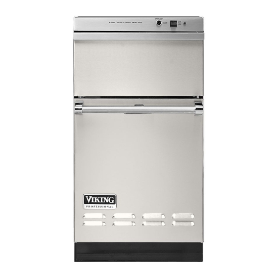
Viking VUC181 Service Notebook
Hide thumbs
Also See for VUC181:
- Use & care manual (8 pages) ,
- Installation instructions (4 pages) ,
- Dimensions & specifications (23 pages)
Table of Contents
Advertisement
Advertisement
Table of Contents

Summary of Contents for Viking VUC181
-
Page 2: Table Of Contents
TABLE OF CONTENTS DUC Cover------------------------------------------------------------------------------------ 00 Table of Contents---------------------------------------------------------------------------- 03 SERVICE INSTRUCTIONS Back Panel---------------------------------------------------------------------------- 04 Side Panel----------------------------------------------------------------------------- 04 Frame Top Assembly---------------------------------------------------------------- 04 Door Front Panel Insert-------------------------------------------------------------- 04 Drawer Assembly--------------------------------------------------------------------- 05 Drawer Latch Mechanism----------------------------------------------------------- 05 Drawer Handle------------------------------------------------------------------------ 05 Drawer Track-------------------------------------------------------------------------- 06 Kick Board----------------------------------------------------------------------------- 06 Control Panel-------------------------------------------------------------------------- 06 Blower Motor-------------------------------------------------------------------------- 07... -
Page 3: Back Panel
SERVICING INSTRUCTIONS SIDE PANELS (Fig. 1) NOTE: IT WILL BE NECESSARY TO REMOVE UNIT FROM 1. Remove top and back panel. INSTALLED POSITION. 2. Open litter bin door and remove two NOTE: DISCONNECT ELECTRICAL retaining screws (9). POWER SUPPLY BEFORE SERVICING 3. -
Page 4: Drawer Assembly
2. Slide panel insert out through opening in 1. Remove drawer. top of litter bin door. 2. Stand drawer on rear and remove the three trim panel retaining screws (1) from bottom of drawer. 3. Remove bottom trim. Slide panel insert out through opening in bottom of drawer front. -
Page 5: Drawer Track
7. When installing drawer tracks, first connect springs to frame (spring hooks facing out), then to track mounting brackets. 8. Force the track downward until the hole in the track mounting bracket lines up with the slot in the frame, permitting installation of the bolt, washer and nut NOTE: At reassembly the bolt head should be on the inside of the frame. -
Page 6: Blower Motor
Remove retaining nut (1) and lock Connect electrical power supply and washer from idler arm. run ram to bottom position. Remove screw (5) from idler plate Disconnect power supply. assy. (4). Shift idler plate to allow idler Remove back panel. arm (3) to clear sprocket cover. -
Page 7: Motor Drive Belt
5. Remove chain (5, Fig.10) from sprocket. 10. Manually rotate motor sprocket 6. Install replacement chain making certain clockwise to check for free operation of chain is properly positioned onto drive ram drive mechanism. and idler sprockets. Install tension regulator spring (4, Fig.10). MOTOR DRIVE BELT To remove: CAUTION: All three drive sprockets must... -
Page 8: Ram Unit
8. Rotate motor sprocket manually approximately two revolutions to align belt. 9. Loosen motor mounting bolts (2, Fig.10), slide motor toward front until belt is taut (approximately 30 to 40 lbs.). 10. Replace chain tension regulator spring (4, Fig.10). RAM UNIT 1. -
Page 9: Jack Screws
7. Remove drawer interlock actuator bracket from rear of upper ram housing. 8. Loosen main wiring harness removing strain relief bushing (1, Fig.14) from frame and harness retainer (4, Fig. 17) from idler plate. 9. Move wiring harness aside. Grasp side of ram and lift from jack screws. -
Page 10: Motor Sprocket & Drive Pulley Assembly
MOTOR SPROCKET DRIVE 9. Remove four motor sprocket bracket PULLEY ASSEMBLY (Fig.17) mounting bolts (1) and lower the drive pulley assembly. 1. Remove top, top frame cover plate and NOTE: Repairs to the motor sprocket and one side panel. drive pulley assembly should not be 2. -
Page 11: Electrical Power Cord
SWITCHES-CONTROL PANEL (Fig.18) 5. Remove electrical power cord. [Filter switch (1), Key lock switch (2)] 6. When reinstalling electrical power cord, feed cord through cord clamps. Remove control panel. Remove lead wires from switches. DIRECTIONAL SWITCH (Fig.18) Remove filter switch by depressing tabs 1. -
Page 12: Interlock Bypass Switch
INTERLOCK BYPASS SWITCH (Fig.10) 1. Remove top and side panel. 2. Remove interlock switch lead wires. 3. Remove switch mounting screws and the switch (2). RAM SWITCH (Fig.19) 1. Remove top and top frame cover plate. 2. Disconnect two lead wires from switch (1). -
Page 13: Pictorial Wiring Diagram
PICTORIAL WIRING DIAGRAM... -
Page 14: Schematic Wiring Diagram
SCHEMATIC WIRING DIAGRAM... -
Page 15: Service Tips
VIKING COMPACTOR ** SERVICE TIPS ** CONDITION POSSIBLE CAUSE REMEDY Motor runs but 1. Motor pulley, motor sprocket, 1.1 Replace pin(s) ram inoperative drive sprocket or drive pulley 1.2 Replace drive belt is inoperative 1.3 Replace drive chain 1.4 Replace pulleys or sprockets Ram stuck in “down”... -
Page 16: Unit Cut-A-Way
DUC180 CUT-A-WAY... -
Page 17: Frame Assembly
DUC180 FRAME ASSY. -
Page 18: Container Assembly
DUC 180 CONTAINER ASSEMBLY... -
Page 19: Ram Assembly
RAM ASSEMBLY... - Page 20 Viking Range Corporation 111 Front Street, Greenwood, Mississippi (MS) 38930 USA (662) 455-1200 Viking products are marketed under the Ultraline brand name in Canada Specifications subject to change without notice F90199 (LP10/02)
- Page 21 Filename: VUC181 21.doc Directory: D:\VBCODE\IPLUTILS\PDFGenerator\InputData\F90568 VUC181 Compactor Template: C:\Documents and Settings\tomw.EYECOM\Application Data\Microsoft\Templates\Normal.dot Title: Subject: Author: Jackie Gibson Keywords: Comments: Creation Date: 10/25/2002 10:23 AM Change Number: Last Saved On: 3/28/2003 4:28 PM Last Saved By: Ken Sievert Total Editing Time:...


Need help?
Do you have a question about the VUC181 and is the answer not in the manual?
Questions and answers
How is the main trash drawer removed from the rest of the unit?
To remove the main trash drawer from the Viking VUC181 unit, follow these steps:
1. Remove the drawer.
2. Stand the drawer on its rear.
3. Remove four retaining screws from the kickboard and the kickboard support plate.
4. Remove the kickboard and support plate.
5. Loosen, then remove the two track mounting nuts and washers (two in front and two in back).
6. Remove bolts and washers.
7. Disconnect springs.
8. Remove the drawer tracks.
These steps ensure the safe and complete removal of the main trash drawer.
This answer is automatically generated