Table of Contents
Advertisement
Advertisement
Table of Contents

Related Manuals for Gesan DVAS 450 E


Summary of Contents for Gesan DVAS 450 E
-
Page 2: Table Of Contents
STANDBY GENERATOR SETS V-6.4 1. WELCOME............................3 2. BASIC SAFETY RULES ...................... 4 3. DESCRIPTION OF GENERATOR SET ....................6 3.1. SOUND INSULATION ......................11 3.2. CONTROL PANEL ........................12 3.3. ELECTRICAL CONFIGURATION................... 15 3.4. RETENTION BATH........................16 4. INSTALLATION OF THE GENERATOR SET ................. 17 4.1. - Page 3 STANDBY GENERATOR SETS V-6.4 6. OPERATION MANUAL ........................33 6.1. CONTROL PANEL COMPONENTS ..................33 6.1.1. Deep sea 4420 digital control module................35 6.1.2. DEEP SEA 7310/7320 Digital Control Module .............. 39 6.1.3. INTELIGEN Digital Control Module ................50 7. MAINTENANCE OF GENERATOR SET..................56 7.1.
-
Page 4: Welcome
STANDBY GENERATOR SETS V-6.4 WELCOME Thank choosing GRUPOS Additionally, you should have received a specific user manual for the Engine and ELECTRÓGENOS EUROPA S.A.generator set. Alternator, electrical setup, a set of keys, ATS The purpose of this manual is to familiarize the (upon order), silencer or exhaust tube and user on how to use and work with the electrical flexible tube (supplied separately for open-skid... -
Page 5: Basic Safety Rules
STANDBY GENERATOR SETS V-6.4 BASIC SAFETY RULES Safety precautions and recommendations for handling the Electrical Generator supplied by GRUPOS ELECTRÓGENOS EUROPA S.A. Do not allow the unit to be used by non-authorized personnel or minors not accompanied by an adult. Use the necessary individual protection equipment. - Page 6 STANDBY GENERATOR SETS V-6.4 Know how to stop the unit in case of emergency. Be special careful with his handling and storage. For refueling the engine, the generator set incorporates an exterior fuel filler neck and cap for filling the tank with diesel.
-
Page 7: Description Of Generator Set
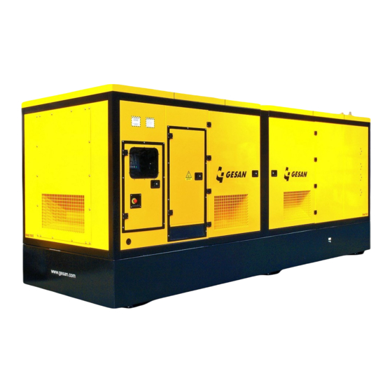
STANDBY GENERATOR SETS V-6.4 DESCRIPTION OF GENERATOR SET Following you have general overview of the generator set (doesn´t match with the delivered genset) and its different configurations manufactured by GRUPOS ELECTRÓGENOS EUROPA S.A. Image 1- Generator set with sound proof canopy. Image 2- Generator set without canopy... - Page 8 STANDBY GENERATOR SETS V-6.4 Image 3- Detailed view of Insonorized genset...
- Page 9 STANDBY GENERATOR SETS V-6.4 1) Coolant tank hatch 9) Canopy 2) Side access door 10) Electrical Panel Doors 3) Fuel tank cap 11) Ventilation grill 4) Exhaust silencer 12) Lifting frame and eyebolt 5) Engine 13) Control panel 6) Shock absorbers 14) Alternator 7) Base frame 15) Electrical power panel...
- Page 10 STANDBY GENERATOR SETS V-6.4 Image 4- Detailed view of openskid genset...
- Page 11 STANDBY GENERATOR SETS V-6.4 6) Base support 1) Lifting frame 7) Control panel 2) Engine 8) Electrical power panel (optional) 3) Shock absorbers 9) Alternator 4) Base frame 10) Battery 5) Fuel tank...
-
Page 12: Sound Insulation
STANDBY GENERATOR SETS V-6.4 3.1. SOUND INSULATION The supplied unit may be: Soundproofed. Includes sound-insulating canopy. Over base support Open skid. You must keep in mind that in compliance with current regulations may require that proper room sound insulation will be provided for this model. (See 4.2 INSTALLATION) Each Electrical Generator is provided with a sticker indicating the level of noise output produced and the need to use hearing protection. -
Page 13: Control Panel
STANDBY GENERATOR SETS V-6.4 3.2. CONTROL PANEL The unit provided may be controlled by different modules depending on the type of function it has been designed to perform. AMMETER (OPTIONAL IN DEEP SEA 4420 CONTROL PANNEL) LOCK EMERGENCY AUTOMATIC BUTTON CONTROL UNIT LOCK DIFFERENTIAL... - Page 14 STANDBY GENERATOR SETS V-6.4 3.2.1. INTELIGEN DIGITAL CONTROL PANNEL I you have adquire a genset with INTELIGEN control panel; the electrical box will have an appearance as shown in the figure below: LOCK EMERGENCY BUTTON LOCK DIFRERENTIAL (OPCIONAL) Image 7-Control panel with InteliGen module...
- Page 15 STANDBY GENERATOR SETS V-6.4 3.2.2. PLACA DIGITAL DE CONTROL DEEP SEA I you have acquire a genset with INTELIGEN control panel; the electrical box will have an appearance as shown in the figure below: AMMETER CERRADURA CERRADURA DIFERENCIAL (OPCIONAL) Image 8-Control panel with DEEP SEA Control module...
-
Page 16: Electrical Configuration
STANDBY GENERATOR SETS V-6.4 3.3. ELECTRICAL CONFIGURATION The supplied unit may be one of three types: The generator unit is supplied with automatic transfer switch (ATS). The generator unit is supplied without ATS. Note that its installation is required. Image 9- Load Transfer diagram Note: PCCB = Power Control Circuit Breaker ATS may be with contactors, motorized changeover switch or motorized circuit breakers... -
Page 17: Retention Bath
STANDBY GENERATOR SETS V-6.4 3.4. RETENTION BATH The generator set may include a built-in retention bath to prevent spills from the unit—such as fuel, oil or coolant—with a capacity of 110% with respect to the total volume of liquids. It is the responsibility of the installer and the owner to take the appropriate measures to avoid contaminants spillage, in case your genset doesn´t includes retention bund and consider that it should have it, please contact with our technical service. -
Page 18: Installation Of The Generator Set
STANDBY GENERATOR SETS V-6.4 INSTALLATION OF THE GENERATOR SET In this part of the manual it is described how to install a “generic” generator set composed of a diesel engine, alternator and electrical panel supplied by GRUPOS ELECTROGENOS EUROPA S.A. For other applications, our technical service will advise. -
Page 19: Intallation Principles
STANDBY GENERATOR SETS V-6.4 4.2. INTALLATION PRINCIPLES 4.2.1. Premises The following considerations must be kept in mind: the fuel supply, ventilation of the premises, the output and direction of the exhaust gases and the noise produced. Dimensions The dimensions should allow for the various required maintenance or disassembly operations. A minimum of one meter should be left on all sides of the generator to allow for the doors to be opened. -
Page 20: Ventilation And Cooling
STANDBY GENERATOR SETS V-6.4 Air intake grill. Will be at least 1.4 times the surface area of the engine’s radiator panel. Smoke exhaust line. This will be explained in more detail later. Silencer. Must be firmly installed and fastened to a stable structure. Smoke exhaust outlet. -
Page 21: Exhaust
STANDBY GENERATOR SETS V-6.4 To install the pump, consult the manual supplied by the client. Note: If unit is positioned beyond the recommended distance, pump should be dismounted and placed near external tank Pump will function if the unit is running; it has an OFF/AUTO switch located on the door of the unit’s electrical panel. 4.2.5. -
Page 22: Generator Set Startup
STANDBY GENERATOR SETS V-6.4 4.2.6. Generator set startup The startup system used by the generator set is electrical and consists of a 12 or 24 V electric engines powered by one or more batteries, usually lead. Low temperatures make engine cranking difficult. Start-up failure (three attempts without success) entails the stopping of the motor and, as a result, of the entire generator unit. -
Page 23: Electrical Connection
STANDBY GENERATOR SETS V-6.4 4.2.7. Electrical connection 4.2.7.1. Safety instructions These connections should be made while following a number of safety measures: Use the proper individual protection equipment to ensure complete safety while performing the electrical installation. Set the control module switch to the OFF position. Make sure the emergency button has been pressed. - Page 24 STANDBY GENERATOR SETS V-6.4 EXIT GENSET MAINS MAINS AUXILARY SYSTEM MAINS 230 V 50 Hz USER CONNECTION Image 14- Connecting external power input -400/230 50 Hz: Phase-neutral connection. -208/120 60 Hz: Phase-phase connection. -220/127 60 Hz: Phase-phase connection. -400/230 60 Hz: Phase-phase connection. -480/277 60 Hz: Phase-neutral connection.
- Page 25 STANDBY GENERATOR SETS V-6.4 Contactors: mechanically and electrically interlocked: They are manufactured from 40A to 125A. Motor operated changeover switches: They are manufactured from 160A. Motor operated circuit breakers: They are supplied only on customer request. The following diagram shows a basic ATS setup. Image 15- ATS setup The electrical installation of the ATS is performed in two separate steps: firstly, the installation of the CONTROL section and secondly, the ELECTRICAL POWER section.
- Page 26 STANDBY GENERATOR SETS V-6.4 ATS schemes: The electrical schemes of a typical ATS manufactured by GRUPOS ELECTRÓGENOS EUROPA S.A. are: ATS by contactors: Image 16- Diagram of ATS Panel...
- Page 27 STANDBY GENERATOR SETS V-6.4 ATS by motorized contacts: Image 17- Diagram of ATS Panel by motorized contactors...
-
Page 28: Installation Of Control Section
STANDBY GENERATOR SETS V-6.4 4.2.7.2. Installation of CONTROL section The installation of the Control section can be done in three different ways: 1) ATS supplied by GRUPOS ELECTRÓGENOS EUROPA S.A. 2) ATS not supplied by GRUPOS ELECTRÓGENOS EUROPA S.A. 3) Unit is a “Standby by signal” type. ATS provided by GRUPOS ELECTRÓGENOS EUROPA S.A. -
Page 29: Installation Of Electrical Power Section
STANDBY GENERATOR SETS V-6.4 Generator unit is “Standby by signal” type: Neither the generator set will monitor the mains nor control the ATS: these must be controlled by the user’s management system. The terminals through which the generator set receives the startup signal are 184 and 185, which should be volt-free. - Page 30 STANDBY GENERATOR SETS V-6.4 In isolated power box gensets, mains cable instalation could be realized by two ways: -Lateral power cables outlet: This way, power cables come out by the trapdoor with protective rubber placed in the control box door, as shown in the image: Lateral power cables inlet.
-
Page 31: Earthing
STANDBY GENERATOR SETS V-6.4 4.2.7.4. Earthing: Ensure that the generator set, including mobile ones, is effectively grounded (earthed) in accordance with every relevant regulation, electrical code, standard or other requirement, prior to start operations. The electrical resistant of earthing installation must be enough low in order to allow earth leakage protection systems to work properly and to limit the voltage in exposed conductive parts, to avoid dangers to people or goods. -
Page 32: Startup
STANDBY GENERATOR SETS V-6.4 STARTUP Prior to start up the generator set, or after making a change in location, you must follow these steps: Check the genset right mechanical balance and the right contact of every base support with the floor. Check and retighten, when necessary, radiator to base frame and radiator to motor screws. -
Page 33: Power Factor And Generator Sets
STANDBY GENERATOR SETS V-6.4 5.1. POWER FACTOR AND GENERATOR SETS The power factor (cos φ) of the generator set loads must be determined. Lagging power factor below 0,8 can overload the generator. It can work properly from 0,8 to 1 lagging power factor. Special attention must be given to installation with power factor corrections equipment (based on capacitors) in order to avoid leading power factor. -
Page 34: Operation Manual
STANDBY GENERATOR SETS V-6.4 Every year the engine / generating set should be run on full load for four (4) hours, to burn off accumulations of carbon in the engine and exhaust system. This may require a “dummy” load. The load should be built-up gradually from zero over the four hour run. ... - Page 35 STANDBY GENERATOR SETS V-6.4 Gauges indicating engine parameters: Oil Pressure Battery charger current Engine Temperature Activated by temperature and fuel button when generator set is stopped. When the generator is Fuel Level operating, the gauges show the corresponding levels. Diagnostic Button: Allows engine parameters to be checked when generator set is stopped (electronically controlled engines).
-
Page 36: Deep Sea 4420 Digital Control Module
STANDBY GENERATOR SETS V-6.4 6.1.1. Deep sea 4420 digital control module Image 20- Deep Sea 4420 Control Module SYÍMBO DESCRIPTIÓN SYMBOL DESCRIPT IÓN Stop / Manual mode Status / Reset button generator set display AUTOMATIC mode (10) Menu button navigator Generator set start up (11) Mains... - Page 37 STANDBY GENERATOR SETS V-6.4 Deep Sea 4420 is an automatic control module that monitors the main power supply; if a mains failure occurs, generator set will start up and loads are transferred. This control module also allows the option of manual startup.
- Page 38 STANDBY GENERATOR SETS V-6.4 MANUAL Mode: The manual mode is activated by pressing the button To begin the starting sequence, press the button. If a mains failure occurs, a remote startup signal is received; loads will be transferred to the generator set. Once the load has been transferred to the generator, it will not be automatically transferred back to the mains supply.
- Page 39 STANDBY GENERATOR SETS V-6.4 Alarm icons Alarm Icon Alarm Icon External input alarm Emergency stop Failed to start Flexible sender alarms Failed to stop Generator contactor alarm Low oil pressure Mains Failure Water temperature Mains Return / Low coolant level Under speed Under voltage Over speed...
-
Page 40: Deep Sea 7310/7320 Digital Control Module
STANDBY GENERATOR SETS V-6.4 6.1.2. DEEP SEA 7310/7320 Digital Control Module Image 21- Deep Sea 7320 Control Module Image 22- Deep Sea 7310 Control Module... - Page 41 STANDBY GENERATOR SETS V-6.4 NUMB SYMBOL DESCRIPTION IDENTIFICATION Stop button. Red LED MANUAL mode Red LED button Green LED (available on TEST mode button model 7320 only) AUTOMATIC mode Red LED button Mute alarm / Lamp test button Generator set start up button “Transfer to Green LED on when...
- Page 42 STANDBY GENERATOR SETS V-6.4 AUTOMATIC mode (AUTO): This is the normal operating mode. The automatic mode is activated by pressing the button (4), at which point the LED at the top of the button will turn on, indicating that it is operational. (7320) If the mains power supply fails for longer than the unit’s programmed period, the LED (7310) If a mains failure occurs, the external management system should send a startup signal to the generator set, at which point the LED indicating remote startup active (8) turns on and the startup process...
- Page 43 STANDBY GENERATOR SETS V-6.4 LOAD TEST mode (7320): A test for proper functioning of the generator set can be done pressing (3). To start up, press the start button (6). In this operating mode, a mains failure is simulated, with the loads being transferred to the generator set. To terminate this mode, press the button (4).
- Page 44 STANDBY GENERATOR SETS V-6.4 INCIDENT ALARM DESCRIPTIONS ALARM Charge alternator voltage not detected Warning Charge failure ALARM Warning Battery under voltage Battery voltage beyond established limits ALARM Warning Battery over voltage ALARM After shutdown command, engine continues running. Warning Could also indicate faulty oil pressure sender Fail to Stop ALARM Auxiliary inputs can be configured and will display the...
- Page 45 STANDBY GENERATOR SETS V-6.4 INCIDENT DESCRIPTION OF SHUTDOWNS ALARM The earth fault current is above shutdown settings (only under Shutdown customer request) Earth fault ALARM Engine does not start, three attempts made. Shutdown Failed to Start ALARM Controlled shutdown of the unit. It will not be functional until the Shutdown emergency stop button has been reset.
- Page 46 STANDBY GENERATOR SETS V-6.4 INCIDENT DESCRIPTION OF ELECTRICAL TRIPS ALARM Generator set current above electrical trip setting. Electrical trip Generator over current ALARM Auxiliary inputs can be configured and will display the message Electrical trip as written by the user Auxiliary inputs ALARM The total kW is above electrical trip setting.
- Page 47 STANDBY GENERATOR SETS V-6.4 Event Log: To view the event log, press the following button repeatedly until the LCD display the event log. It registers the shutdown alarms occurring in the generator unit. A screen similar to this is shown: “On September 12, 2007, at 08:25:46, the unit detected that the oil pressure was below the minimum level and has shut down the generator.
- Page 48 STANDBY GENERATOR SETS V-6.4 If no buttons are pressed upon entering an instrumentation page, the instruments will be displayed automatically. Alternatively, by pressing on buttons, the user can scroll through all the instruments on a particular screen. This disables autoscroll. When autoscroll is disabled, if no buttons are pressed the display will return to the status page.
- Page 49 STANDBY GENERATOR SETS V-6.4 Generator load (kW) Generator load (kVA) Generator power factor Generator load (kVAr) Generator load (kWh, kWAh, kVArh) Generator phase sequence Mains (DSE 7320 only) Mains voltage L-N Mains voltage L-L ...
- Page 50 STANDBY GENERATOR SETS V-6.4 Editing the current Date and Time: The date and time are adjustable. When the battery is disconnected, the date and time are frozen; when the battery is reconnected, the date and time shown will be from the last time the battery was disconnected. The date and time reflected in the Event Log will be taken from the configuration according to the following steps: Press...
-
Page 51: Inteligen
STANDBY GENERATOR SETS V-6.4 6.1.3. INTELIGEN Digital Control Module Image 23- INTELIGEN Digital Control Module SYMBOL DESCRIPTION IDENTIFICATION OFF←MAN←AUT←TEST Scrolls through different operating OFF→MAN→AUT→TEST modes Deactivates audible alarm Fault reset Acknowledges faults and alarms Start button In manual mode Stop button In manual mode MCB ON/OFF Opens and closes MCB in manual mode... - Page 52 STANDBY GENERATOR SETS V-6.4 Moves history record 6.1.4. Increases value (12) displayed columns to right/left, increase/decrease edited set point, a value (13) Decreases value or go out/into alarm list. (14) Enter button Confirms on-screen value (15) Mains power status Green if mains power correct Red light flashes if mains failure occurs and generator set (16) Mains failure...
- Page 53 STANDBY GENERATOR SETS V-6.4 or parameters on each screen menu, press (10) or (11) buttons. To come back to a previous menu screen, press . (9) button. The alarmlist screen display the alarms detected by the module. Pressing button (4) faults and alarms are acknowledged.
- Page 54 STANDBY GENERATOR SETS V-6.4 NO-LOAD TEST mode (MANUAL): Press the START button (5) to start up the generator set. When the generator voltage is within the established limits, the LED indicator (17) will be on. To stop the unit, press STOP (6).
- Page 55 STANDBY GENERATOR SETS V-6.4 ALARMS: The InteliGen control module includes the following warnings: INCIDENT STORED IN HISTORY RECORD Startup sequence initiated Startup of Gen-Set Shutdown of the Gen-Set Gen-Set stops Electrical Generator circuit breaker closed GCB connected Electrical Generator circuit breaker opened GCB disconnected Some GCB in group was opened (in MINT) Other GCB trip...
- Page 56 STANDBY GENERATOR SETS V-6.4 GENERATOR EVENT SPECIFICATION HISTORY Generator phase 1 overvoltage Unl Vg1 Over Generator phase 1 undervoltage Unl Vg1 Under Generator phase 2 overvoltage Unl Vg2 Over Generator phase 2 undervoltage Unl Vg2 Under Generator phase 3 overvoltage Unl Vg3 Over Generator phase 3 undervoltage Unl Vg3 Under...
-
Page 57: Maintenance Of Generator Set
STANDBY GENERATOR SETS V-6.4 MAINTENANCE OF GENERATOR SET You must make sure that the person who will perform this duty is qualified to do so and uses the appropriate individual protection equipment. 7.1. PRIOR TO MAINTENANCE You must first: Switch Control Module to the OFF position. - Page 58 STANDBY GENERATOR SETS V-6.4 The Engine oil level shall also be checked periodically. This will be accomplished by pulling out the dipstick. It shall be carried out with the engine cold and in a horizontal position. If you wish to check the oil level upon shutting down the Engine, wait for the housing to drain prior to checking the oil level.
- Page 59 STANDBY GENERATOR SETS V-6.4 The radiator coolant level should be adequate. The fuel level in the tank should be sufficient for the service to be performed. In the DEEP SEA 4420 generator control panel is equipped with a fuel gauge, which will be functional whenever the electrical panel is receiving power.
- Page 60 STANDBY GENERATOR SETS V-6.4 when acid density is 1.28. Before completing recharging process: turn off charger before disconnecting battery and check electrolyte level. If the battery is discharged and you want to perform an emergency startup with the battery from another generator, first check the tightness of the discharged battery’s terminals. Stop the engines of both units and connect the two positive terminals of the batteries first and then connect the negative terminal of the charged battery to a metal area on the disabled unit (ground).
-
Page 61: Maintenance Chart
STANDBY GENERATOR SETS V-6.4 7.3. MAINTENANCE CHART FREQUENCY MAINTENANCE OPERATION Perform a mains failure simulation; the unit should supply power to consumers for one hour. For parallel units, check the connection and the load sharing. Review the connections of the startup battery, clean and cover with vaseline. Make sure the battery charger is functioning properly. -
Page 62: Troubleshooting
STANDBY GENERATOR SETS V-6.4 TROUBLESHOOTING INCIDENT LIKELY CAUSE SOLUTION 1.-Defective battery 1.-Replace battery Starter does not 2.-Replace starting system 2.-Defective starting turn system 3.-Contact technical service. 1.-Faulty voltage detector on control 1.-Contact technical service. Starter functioning properly module 2.-Low fuel level 2.-Refill fuel tank 1.-Emergency has Stops with cause... -
Page 63: Protection From The Environment
STANDBY GENERATOR SETS V-6.4 PROTECTION FROM THE ENVIRONMENT Once the generator set has been installed, it is necessary to remove the packaging, accessories, electrical tools, etc., that were used during the installation process. When it is time to dispose of the batteries, in keeping with environmental regulations it is advisable to take them to an authorized recycling center. -
Page 64: Noise Level
STANDBY GENERATOR SETS V-6.4 Any repair made within the warranty period shall not lead to the modification of expiry date for the generator set warranty. The warranty does not cover damages caused by terrorist acts, natural disasters, sabotages or similar occurrences. -
Page 65: Appendix 1: Figures
V => Engine manufacturer is (V)olvo, (P)erkins, (C)ummins, Mitsubis(H)I or M(T)U. A => The generator set is automatic DVAS 450 E S => The generator set is soundproofed 450 => Commercial name E => Indicates generator set is standby type Rated power Rated power of generator set expressed in kW. - Page 66 STANDBY GENERATOR SETS V-6.4 Image 27:This genset may Image 29:Undefined Image 28:General warning start without prior warning warning notice Image 31: Electrical Image 32: Electrical Image 30: Electrical hazard hazard 230 Volts hazard 400 Volts Image 33: Possible spillage Image 34:Electrical Image 35:Noise output of battery acid grounding...
-
Page 67: Appendix 2: Image Index
STANDBY GENERATOR SETS V-6.4 APPENDIX 2: IMAGE INDEX Image 1- Generator set with sound proof canopy....................6 Image 2- Generator set without canopy........................6 Image 3- Detailed view of Insonorized genset ......................7 Image 4- Detailed view of openskid genset ......................9 Image 5- Noise output pictograms and hearing protection required .............. -
Page 68: Appendix 3: Pre-Delivery Inspection Document
STANDBY GENERATOR SETS V-6.4 APPENDIX 3: PRE-DELIVERY INSPECTION DOCUMENT... -
Page 69: Appendix 4: Derating Of Engine Power Rating
STANDBY GENERATOR SETS V-6.4 APPENDIX 4: DERATING OF ENGINE POWER RATING: Engine power rating is declared for the following conditions in accordance with the norms ISO-8528-1:2005 and ISO-3046-1:2002. - Air pressure: 100 kPa - Temperature: 25ºC - Relative humidity: 30% If site ambient conditions are different from standard, derating of engine power rating is possible. - Page 70 STANDBY GENERATOR SETS V-6.4 16.2. DERATING OF ENGINE POWER RATING OF TURBOCHARGED ENGINES WITH CHARGE AIR COOLING: Altitude from sea Barometric pressure Temperature (ºC) 101,3 1,28 1,22 1,19 1,16 1,13 1,11 1,08 1,06 1,04 1,01 0,99 0,97 100,1 1,27 1,21 1,18 1,15 1,12 1,10 1,07 1,05 1,03 1,00 0,98 0,96 99,5 1,26 1,20 1,17 1,14 1,12 1,09 1,07 1,04 1,02 1,00 0,98 0,96 98,7...
- Page 71 STANDBY GENERATOR SETS V-6.4 16.3. DERATING OF ENGINE POWER RATING OF NATURALY ASPIRED ENGINES: Humidity: 30% Altitude from sea Barometric pressure Temperature (ºC) 101,30 1,14 1,10 1,09 1,07 1,05 1,03 1,02 1,00 0,98 0,97 0,95 100,00 1,12 1,09 1,07 1,05 1,03 1,02 1,00...
- Page 72 STANDBY GENERATOR SETS V-6.4 NOTAS:...
- Page 73 STANDBY GENERATOR SETS V-6.4...
- Page 74 STANDBY GENERATOR SETS V-6.4...
- Page 75 STANDBY GENERATOR SETS V-6.4...
- Page 76 RUPOS ELECTRÓGENOS EUROPA, S.A.
Need help?
Do you have a question about the DVAS 450 E and is the answer not in the manual?
Questions and answers