Table of Contents
Advertisement
CAUTION
!
It is strongly recommended that shielded
wiring be used for ALL impulse meter
connections. The use of unshielded
wiring could results in erroneous dispense
volumes. The Director batch register
and the totaling register will read the
correct amounts requested, but the
actual dispense volume will be less. This
condition is a result of the unshielded
wiring picking up stray signals from
adjoining electrical wires and/or electrical
equipment. If unshielded wiring is used,
the condition described above will not
be covered under Balcrank's Product
Warranty.
Thoroughly read and understand this manual before
installing, operating or servicing this equipment.
OPERATION, INSTALLATION,
MAINTENANCE AND REPAIR GUIDE
SERVICE BULLETIN SB3101
Rev. B 6/16
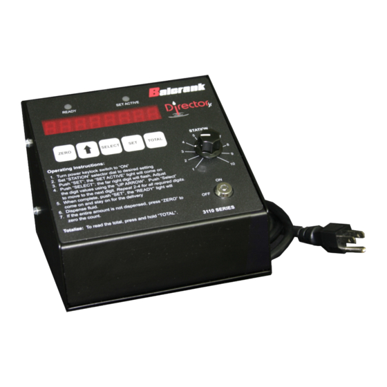
Director Jr.
Model #3110-031
24V DC Output
®
Advertisement
Table of Contents
Troubleshooting

Related Manuals for Balcrank Director Jr. 3110-031


Summary of Contents for Balcrank Director Jr. 3110-031
- Page 1 If unshielded wiring is used, the condition described above will not be covered under Balcrank’s Product Warranty. Thoroughly read and understand this manual before installing, operating or servicing this equipment.
-
Page 2: General Safety Information
GENERAL SAFETY REQUIREMENTS NOTE: THOROUGHLY READ AND UNDERSTAND THIS MANUAL BEFORE INSTALLING, OPERATING, OR SERVICING THIS EQUIPMENT. WARNING IMPORTANT Check equipment regularly and DANGER: Not for use with fluids repair or replace worn and that have a flash point below 100°F damaged parts. (38°C). Examples: gasoline, alcohol. Sparking could result in an explosion which could result in death. Never alter or modify any part of this unit, doing so may cause damage to the unit and/or personal injury. -
Page 3: Table Of Contents
TABLE OF CONTENTS General Safety Information..........................1 Introduction ...............................3 General Description ............................3 System Specifications ............................3 Console Features ...............................3 Product Specifications.............................4 Operational Schematic ............................4 Interconnection Box ............................5 Impulse Meter ..............................5 Installation .................................5 General ................................5 Plumbing................................5 Electrical ................................6 Wiring Diagram ..............................7 Console Setup ..............................8 Pulse Calibration Factor .............................9 Post Installation Check ..........................10 Operational Check ............................10 Operation Instructions ...........................10 Normal Operation .............................10... -
Page 4: Introduction
INTRODUCTION General Description Controlled dispensing of motor oil, ATF, gear oil, and antifreeze is available with the electrical DIRECTOR JR. The unit allows the selection of one of up to ten (10) stations. One Director Jr. is required for each fluid type dispensed. The console size is very small allowing for easy placement of as many units as may be required for the number of fluids to be dispensed. Each unit is completely self-contained. The units of measure can be set to quarts, pints, liters, or gallons. The voltage controlling the solenoid valves and the impulse meter is 24 VDC. -
Page 5: Product Specifications
3. Air Regulator - To regulate air pressure to the pump, so not to exceed 80 psi and/or limit pump output pressure to 850 psi (59 bar) if normal air supply would make it higher than recommended. 4. Air Solenoid Valve (3120-033) - This valve opens and closes air line to start the pump when activated by the Director Jr. (Balcrank recommends this feature to help prevent accidental spills.) 5. Pumps - 1.3:1, 3:1, 5:1, and 10:1 ratios can provide and maintain sufficient line pressures and fluid volumes for most systems (system plumbing length will dictate pump ratio required). 6. Impulse Meter (3120-114) - Electric impulse meter measures the amount of fluid that is being dispensed. System can be set to measure in quarts, liters, pints, or gallons. -
Page 6: Interconnection Box
Interconnection Box There is no interconnection box or junction box provided with the Director Jr. because all of the electronics are contained in the console. A multiwire cable is provided to connect in any convenient wiring box. Impulse Meter An impulse meter is used in the system to measure the amount of fluid dispensed. This meter is actually a simple flow meter that is installed in the fluid line. Inside the impulse meter is a rotating cam that actuates a small microswitch that sends electrical impulses to the console. This meter can measure in quarts, pints, liters or gallons. INSTALLATION General To determine the installation requirements for a Director Jr. system(s), certain factors need to be established. In general, these factors will determine how much material such as cable wire, fluid lines, pumps, and etc. will be needed. Answers to these questions below will help determine your material requirements. 1. Determine how many fluid types are to be dispensed. This will determine how many Director Jr. systems will be needed. -
Page 7: Electrical
The electric fluid solenoid valve (3120-032) is installed in the hydraulic line as near to the point of dispensing as possible (Figure 1, Item 11). One valve must be installed in the line of each outlet to be controlled. It is sug- gested that a manual by-pass valve be installed around the solenoid valve as shown in the diagram (Figure 1, Item 9). This allows the solenoid valve to be by-passed in case of electric power line failure. The by-pass valve should allow for locking in either the open or closed position by means of a padlock or sealing wire to avoid tampering. ELECTRICAL Refer to Figures 2 and 3 for electrical installation. Installation should be made in accordance with the National Electrical Code (NFPA 70) and the Flammable and Combustible Liquids Code (NFPA 30). Power input to the Director Jr. is 110 VAC. All control circuits are 24 VDC which are not normally restricted by electrical codes, however, local codes should be checked for applicability, and all electrical installations should comply with codes. -
Page 8: Wiring Diagram
CAUTION Before attempting to operate the system a careful check should be made of all wiring to assure that all connections are secure and that no frayed leads cause an unwanted connection between terminals or leads. - Page 9 SETUP INFORMATION General Director JR. 3110-031, VDC comes preprogrammed with pulse settings from the factory (see Table 1 below). Units shipped from the factory come pre-set for quarts. When the system is powered on, the display will indicate: - the current system settings with a delay of 2 seconds (see image 2 below) - the total ammount dispensed with a delay of 2 seconds - normal operation display (see image 1 below) Image 1 - Normal operation display Image 2 - Current System Settings;...
-
Page 10: Console Setup
CONSOLE SETUP INFORMATION (CONTINUED) Entering the Setup Menu: - Start with the unit powered OFF - While pressing the “Zero” and “Up arrow” buttons, power on unit by turning key to “ON” position. SETUP DISPLAY Units Pulse # Pulses Calibration per unit Factor Pulse Calibration Factor: - Can be set to 1 through 5, or negative 1 through 5, allowing you to adjust pulses per unit up or down 5 pulses. -
Page 11: Post Installation Check
POST INSTALLATION CHECK If manual by-pass valves have been installed at the solenoid valves (Figure 1, Item 9), they should be opened to allow checking the system for leakage before the electrical check out. The pumps should be set to operate at normal pressure (500 psi maximum), and oil drawn from each dispensing point. When it is certain that all air and foreign materials have been purged from all lines, the piping system should be checked for leaks. The by-pass valves should be closed before proceeding with the electrical check out. -
Page 12: Totalizer Operation
Totalizer Operation The totalizer will accumulate and display the pulses received on the count input terminals. The Totalizer is factory preprogrammed with a decimal value of 0.1, but it displays only the whole number accumulations that are also indicated on the dispense counter (e.g. 120.3 on the dispense counter = 120 on the Totalizer). Count capacity is 8 digits. To read the total, press and hold “TOTAL”. Key lock Operation The Director Jr. is equipped with a security key lock to enable the system. The key must be inserted and turned to the ON position (12 o’clock position) to enable dispensing. The Director Jr. should have power applied prior to turning on the key lock switch to assure that the controller is initialized. -
Page 13: Service And Maintenance
General No attempt should be made to repair the Director Jr. console unit. A certain amount of information about servicing and troubleshooting is provided in this manual but if questions arise, contact your Balcrank Service Representative or the Balcrank factory Service Department. Customer repairs that are beyond the scope of this manual become the sole responsibility of the customer. -
Page 14: Troubleshooting Chart
TROUBLESHOOTING CHART In order to properly troubleshoot the system and perform proper replacement or repair of parts, it is neces- sary that the technician performing the work be thoroughly familiar with the equipment. Attempted repair by unqualified personnel could void the warranty. It is suggested that this manual be studied thoroughly before any troubleshooting is attempted. It is suggested that whenever there is a problem with the system that a visual inspection first be made of the overall condition of the equipment. - Page 15 Symptom Cause Solution 5. System has power and Pump is not operating. Check the air supply to the pump goes into ready mode, and the pump air solenoid valve. but no fluid can be dispensed. Out of fluid. Check the fluid level in the storage container. Control solenoid valve not Check valve for energized position. operating.
-
Page 16: Factory Service
The unit should be returned to a Balcrank autho- rized Service Center for repair or adjustment. - Page 17 NOTES:...
-
Page 18: Warranty Statement
For Warranty Information Visit: www.balcrank.com Balcrank Corporation ® Weaverville, NC 28787 800-747-5300 800-763-0840 Fax www.balcrank.com SERVICE BULLETIN SB3101 Rev. A 2/15...
Need help?
Do you have a question about the Director Jr. 3110-031 and is the answer not in the manual?
Questions and answers