
Related Manuals for Drive Delta 1000


Summary of Contents for Drive Delta 1000
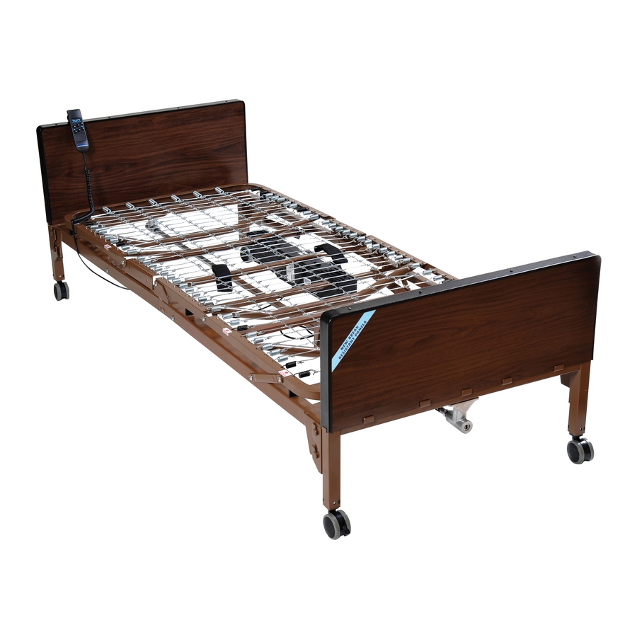
- Page 1 Delta 1000 Ultra Light Plus, Semi Electric Bed Item # 15030 Owner’s Assembly And Operating Manual REV3.1.14.16...
-
Page 2: Assembly Instructions
Assembly Instructions Confirm that all parts are present. A. Foot Spring B. Head Spring C. Head Board D. Foot Board E. Hi/Low Shaft F. Locking Pins G. Motor H. Hand Crank (attached to foot board for shipping) I. Casters (4) - 2 locking, 2 non-locking J. - Page 3 Assembly Instructions Cont. 1. Install drive shaft onto foot section. Thumb Screw 2. The lock collar comes pre-set from the factory. Ensure that it is 1/4” - 1/2” away from hanger bracket. If not, slide lock collar 1/4” from the foot side of the hanger bracket as shown.
- Page 4 Assembly Instructions Cont. Continued 4. With bed on side extend the shaft until it reaches the full length of bed. a. NOTE: The shaft adjustment holes are marked to indicate the style (semi/full) of bed the shaft is being installed on.
- Page 5 Assembly Instructions Cont. 5. Insert lock pin through connected sleep surface and secure with spring clip. 5A. Connect head section and foot section by squeezing together and attaching with spring links. Pull up the head section and foot section to release tension between the springs.
- Page 6 Assembly Instructions Cont. HAND CONTROL The Delta bed comes with a hand control that will illuminate when the bed is plugged into a grounded or polarized wall outlet, or with 9V battery (sold separately) installed in the hand control. The hand control will illuminate as long as the wall or battery has power.
- Page 7 Assembly Instructions Cont. There are two methods for the installation of the motor Method A The motor is installed on the bed frame when the frame is standing on its side. Installation instructions can be found on pages 8-9. Method B The motor is installed from underneath the bed frame (horizontal to the ground) Installation instructions can be found on pages 10-11.
- Page 8 Assembly Instructions Cont. Method A Installation of the motor when bed frame is on its side A1. Prior to installation, make sure that the 2 white motor blocks are in the retracted position. CORRECT INCORRECT A2. Align the opening on the head end of the Actuator Bar motor with the flange on the head section of the bed and insert the flange into the motor...
- Page 9 Attach the foot board and head board as shown. NOTE: The head section is higher than the foot section. However, they are interchangeable with each other, with all other Drive and other manufacturers head and foot boards. End Method A Go To Page 12, Step 8...
- Page 10 NOTE: The head section is higher than the foot section. However, they are interchangeable with each other, with all other Drive and other manufacturers head and foot boards. B3. Prior to installation, make sure that the 2 white motor blocks are in the retracted position.
- Page 11 Assembly Instructions Cont. Method B Continued Actuator Bar B4. With the motor orientated properly with the bed (head to head, foot to foot), align the motor with actuator bar and lift the head spring to the highest position. The motor will automatically be pulled towards the bed and lock onto the actuator.
- Page 12 Assembly Instructions Cont. 8. Install Hi/Low shaft to the foot section of the bed by inserting the spring loaded side of the shaft to the bottom receptacle as shown. Spring Loaded Shaft 8A. Based on the bed end configuration, install the shaft into the proper port to ensure correct bed hi/low function.
- Page 13 Spring Loaded Shaft NOTE: Transition box is pre-set from factory but if using a non-Drive head or foot board, and the shaft that extends from the crank housing is too long or short, the transition box can be adjusted with a 6mm allen key.
- Page 14 Bed Rail Installation NOTE: USE DRIVE APPROVED RAILS ONLY 11. Attaching Bed Rails a. Half rails • The head section features labels on the frame marked, “INSTALL HALF RAILS HERE” and black springs for proper placement. b. Full Rails •...
-
Page 15: Height Adjustment
Height Adjustment 12. To raise the height of the bed, remove the crank that is attached to the bottom of the foot board. Crank Crank Housing 13. Insert into the receptacle. 14. Turn clockwise to raise the height of the bed, counter clockwise to lower the height of the bed. - Page 16 Optional Fixed Height Adjustment 15. Optional fixed height adjustment with lock pins 16. The four large pins are used if the height of the bed is to be locked at a set height. Set the height of the bed so that the hole in the leg is aligned with the hole in the bed end outer leg.
- Page 17 Storage 18. Shown on Bed Storage Transporter (model # 15060) with motor attached with storage straps (included). Storage Straps...
- Page 18 5 year warranty on frame. • 5 year warranty on motor. • 5 year on hand control. • 1 year warranty on all other parts and components. During the warranty period, defective items will be repaired or replaced at Drive’s option at no charge.
-
Page 19: Specifications
Specifications DECK HEIGHT BED HEIGHT (HIGH POSITION) 21.5” 21.5” 21.5” 87.5” 87.5” 87.5” 80” MATTRESS BED HEIGHT REQUIRED (LOW POSITION) LENGTH 15.5” 15.5” 15.5” DECK WIDTH ELECTRICAL • Motor is UL approved. WEIGHT • Normal operating conditions: 450 lbs evenly distributed. CONSTRUCTION •... - Page 20 Drive Medical products are specifically designed on raised head or foot sections of the bed. This and manufactured for use in conjunction with Drive includes when assisting the user in repositioning or Medical accessories. Accessories designed by transferring in or out of bed.
- Page 21 WARNINGS Keep the product a minimum of 12 inches away The total weight limit of the Drive Medical 36-inch from any direct heat source. (91.4 cm) wide Manual/Electric bed (including accessories, mattress, occupant and any other Make sure head and foot springs/sections are con-...
- Page 22 Drive Medical recommends that the mattress be centered on the bed frame. Otherwise, individuals ELECTRICAL WARNINGS may become entangled between the bed rail and A safety feature of this product includes protec- the bed frame.
- Page 23 WARNINGS cians are permitted to repair these parts. If unquali- the bed to a service center for examination and fied individuals perform any work on these beds, repair. the warranty is void. On Full Electric beds, the Hi/Lo crank MUST be DO NOT place pendant under or between objects.
- Page 24 WARNINGS DO NOT use near explosive gases. from the bed. This may damage the frame and/or motors and create a danger to the patient. Possible fire hazard when used with oxygen ad- ministering equipment other than nasal or masked DO NOT attempt to raise the Head (Head Spring) type.
- Page 25 Notes:...
- Page 26 Notes:...
- Page 28 99 Seaview Boulevard Port Washington, NY 11050 Phone: 516-998-4600 Toll Free: 877.224.0946 Fax: 516.998.4601 www.drivemedical.com REV3.1.14.16...
Need help?
Do you have a question about the Delta 1000 and is the answer not in the manual?
Questions and answers