
Related Manuals for Festo SFC-DC series


Summary of Contents for Festo SFC-DC series
- Page 1 Motor controller SFC−DC Manual Electronic Motor controller type SFC−DC−...−IO Manual 540 418 en 0801a [731 438]...
- Page 2 ® ® Adobe and Reader are either a registered trademark or a trademark of Adobe Systems Incorporated in the United States and/or other countries.
- Page 3 ....... . . 540 418 E (Festo AG & Co. KG, D 73726 Esslingen, Federal Republic of Germany, 2008) Internet: http://www.festo.com...
- Page 4 Contents and general instructions Festo P.BE−SFC−DC−IO−EN en 0801a...
-
Page 5: Table Of Contents
....1−17 1.3.2 Festo Configuration Tool (FCT) ......1−17 Fitting . - Page 6 ..... 5−23 5.4.1 Installing and starting the Festo Configuration Tool ... . 5−23 5.4.2 Procedure for commissioning with the Festo Configuration Tool 5−24 Festo P.BE−SFC−DC−IO−EN en 0801a...
- Page 7 ..........B−11 Festo P.BE−SFC−DC−IO−EN en 0801a...
- Page 8 ............C−1 Festo P.BE−SFC−DC−IO−EN en 0801a...
-
Page 9: Designated Use
Please observe the standards specified in the relevant chapters and comply with technical regulations, as well as with national and local regulations. Festo P.BE−SFC−DC−IO−EN en 0801a... -
Page 10: Safety Instructions
Warning Faults in parametrization can cause injury to people and damage to property. Enable the controller only if the axis system is correctly installed and parametrized. VIII Festo P.BE−SFC−DC−IO−EN en 0801a... -
Page 11: Target Group
Service Please consult your local Festo repair service at the following e−mail address if you have any technical problems: service_international@festo.com Scope of delivery The scope of delivery of the Single Field Controller type SFC−DC includes the following:... -
Page 12: Important User Instructions
This means that failure to observe this instruction may result in damage to property. The following pictogram marks passages in the text which describe activities with electrostatically sensitive compo nents. Electrostatically sensitive components may be damaged if they are not handled correctly. Festo P.BE−SFC−DC−IO−EN en 0801a... - Page 13 Accessories: Information on necessary or sensible accessories for the Festo product. Environment: Information on environment−friendly use of Festo products. Text markings The bullet indicates activities which may be carried out in · any order. 1. Figures denote activities which must be carried out in the numerical order specified.
-
Page 14: Manuals For The Single Field Controller Sfc−Dc
Single Field Controller type SFC−DC−..It also contains information on the functions of the I/O interface for type SFC−DC−...−IO as well as on commissioning with the Festo Configuration Tool software package. Product variants are available for coupling to field bus sys tems. - Page 15 SFC−DC. You can find the specifications on the version status as follows: Hardware version and firmware version in the Festo Configuration Tool with active device connection to the SFC−DC under Device data" Firmware version on the control panel under [Diagnostic] [Software information].
-
Page 16: Product−Specific Terms And Abbreviations
The special wishes of a device type are supported by plug−ins with the necessary descriptions and dialogues. Input Output Input and/or output Positioning mode Operating mode for processing a position set. (Profile Position mode) Programmable logic controller; in brief: controller. Festo P.BE−SFC−DC−IO−EN en 0801a... - Page 17 Tip mode Manual positioning in positive or negative direction (only on field bus variants of the SFC−DC via the field bus or only with FCT or operator panel) Tab. 0/1: Index of terms and abbreviations Festo P.BE−SFC−DC−IO−EN en 0801a...
- Page 18 Contents and general instructions Festo P.BE−SFC−DC−IO−EN en 0801a...
-
Page 19: System Summary
System summary Chapter 1 1−1 Festo P.BE−SFC−DC−IO−EN en 0801a... - Page 20 ....1−17 1.3.2 Festo Configuration Tool (FCT) ......1−17 1−2...
-
Page 21: Positioning With Electric Drives
Coupling to a higher−order PLC/IPC can be accomplished via digital inputs/outputs (SFC−DC−...−IO) or with the appropriate product variants via the field bus (in preparation: DeviceNet, CanOpen, PROFIBUS−DP). For positioning systems Festo offers accessories suited to the drive packages and linear drives (see Festo delivery program or catalogue). 1−3... - Page 22 1. System summary Components Higher−level controller e.g. Festo type FEC... Software level: Festo Configuration Tool Controller level: SFC−DC Motor drive level: SLTE−... Fig. 1/1: Principle of an electric axis with the SFC−DC−... 1−4 Festo P.BE−SFC−DC−IO−EN en 0801a...
- Page 23 SFC−DC (see accessories, appendix A.2). Reference switch Optional: suitable sensor (normally open) as reference switch, e.g. type SME−10/SMT−10. The SFC−DC supports the electric mini−slide SLTE−..Consult Festo if you wish to use other drives. Supported Manual Permitted drive...
- Page 24 (Teach mode) Positioning travel for testing all position sets in the posi tion set table (Demo posit. tab.) Positioning travel for testing a certain position set in the position set table (Move posit. set.) 1−6 Festo P.BE−SFC−DC−IO−EN en 0801a...
- Page 25 (measurement of the power end stage temperature) voltage monitoring detection of faults in the logic voltage supply detection of faults in the logic voltage supply t monitoring / overload protection following error monitoring software end position recognition. 1−7 Festo P.BE−SFC−DC−IO−EN en 0801a...
-
Page 26: Structure Of The Sfc−Dc
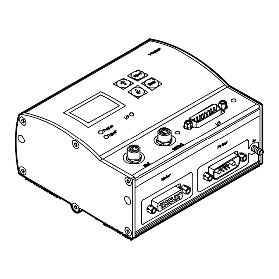
Remove the protective foil from the display before commis sioning. LC display Touch−sensitive keyboard LEDs Fig. 1/3: Control panel and status display on the SFC−DC−...−H2−... 1−8 Festo P.BE−SFC−DC−IO−EN en 0801a... - Page 27 (= interface / field bus) Fault Error" Connections The SFC−DC has the following connections: Reference switch RS232 interface to PC I/O interface Power Electric mini−slide Error SLTE−... Power supply RS–232 3 4 5 Fig. 1/4: Connections of the SFC−DC 1−9 Festo P.BE−SFC−DC−IO−EN en 0801a...
-
Page 28: Method Of Operation
Fig. 1/5: Simplified technical representation of the cascade regulator function The controller takes over the following tasks: sequence control via digital inputs and outputs (type SFC−DC−...−IO) specification of the nominal positions by positioning control control of the following variables: Position, speed, acceleration, current (power). 1−10 Festo P.BE−SFC−DC−IO−EN en 0801a... - Page 29 20F1 (Data memory control) (see chapter 7). User−specific settings will then be lost. Use CI commands only if you already have experience of · Service Data Objects. If necessary consult the Festo Service. · 1−11 Festo P.BE−SFC−DC−IO−EN en 0801a...
-
Page 30: Reference Coordinates And Working Area
The project zero point is specified for the SFC−DC with I/O interface, and is identical to the axis zero point (project zero point offset = 0). 1−12 Festo P.BE−SFC−DC−IO−EN en 0801a... - Page 31 Rated stroke: Rated stroke of the drive used, see Technical Specifications for the drive (with SLTE the stroke specified in the order). Vector representation for the referencing method: Example of fixed stop, negative Tab. 1/2: Measuring reference system of the electric axis 1−13 Festo P.BE−SFC−DC−IO−EN en 0801a...
- Page 32 Negative values face from the reference point in the direction towards the motor. Factory setting (see also appendix B, object 607E) All values are entered or displayed according to the measur ing system set either for the Festo Configuration Tool or the control panel. Measuring system Linear axis Metric Metric measuring units e.g.
-
Page 33: Emergency Stop Concept
By the arrangement of the software end positions and, if · necessary, by means of external safety limit switches and additional appropriate mechanical stops, make sure that the axis always lies within the permitted positioning range. 1−15 Festo P.BE−SFC−DC−IO−EN en 0801a... -
Page 34: Commissioning Options
Commissioning Reference travel Teaching of positions Moving in individual steps Starting and stopping positioning procedures during commissioning Expanded test functions, e.g. status displays Testing or demonstrating the position sets Diagnosis/Service Reading and displaying diagnostic data 1−16 Festo P.BE−SFC−DC−IO−EN en 0801a... -
Page 35: Control Panel (Only Type Sfc−Dc−...−H2−...)
4, a description of commission ing with the control panel as from chapter 5.3. 1.3.2 Festo Configuration Tool (FCT) The Festo Configuration Tool (or brief FCT) is the software platform for configuring and commissioning different compo nents or devices from Festo. - Page 36 An overview of commissioning with the FCT can be found in chapter 5.4.2. The help for the FCT contains the complete information on operating the Festo Configuration Tool. The device−specific PlugIns each have their own help files. You can use the complete help or parts thereof irrespective of a PC by printing them.
- Page 37 1. System summary The help system of the Festo Configuration Tool The Festo Configuration Tool offers various possibilities of obtaining information or help with operation. Install and start the program as described in chapter 5. · FCT help You can open the help for the FCT as follows: Access the help in the menu [Help] with the command ·...
- Page 38 Printed version Directory File FCT help ...(FCT installation directory)\Help\ FCT_en.pdf FCT_en.rtf PlugIn help ...(FCT installation directory)\HardwareFamilies\ SFC−DC_en.pdf (SFC−DC) Festo\SFC−DC\V...\Help\ SFC−DC_en.rtf For using the print version in the Adobe PDF format you will require the Adobe Reader. 1−20 Festo P.BE−SFC−DC−IO−EN en 0801a...
-
Page 39: Fitting
Fitting Chapter 2 2−1 Festo P.BE−SFC−DC−IO−EN en 0801a... - Page 40 ........2−6 2−2 Festo P.BE−SFC−DC−IO−EN en 0801a...
-
Page 41: General Instructions
The specified torques must be observed. The modules must not be offset. Contact surfaces must be clean (avoid contact faults). Dimensions of the controller 126 mm 120 mm Power Error RS–232 Fig. 2/1: Dimensions of the controller 2−3 Festo P.BE−SFC−DC−IO−EN en 0801a... -
Page 42: Fitting The Controller
The four brackets are clipped onto the edge of the housing (see Fig. 2/2). 4 threaded holes for screw size M3 (for dimensions see Fig. 2/2) with suitable screws. 120 mm Power Error RS−232 approx. 105 Fig. 2/2: Screwing the SFC−DC to the wall 2−4 Festo P.BE−SFC−DC−IO−EN en 0801a... - Page 43 When you let go, the clamping element presses the SFC−DC into the upper groove. Top−hat rail Clamping element Distance between housing web and top−hat rail: 3.3 mm Fig. 2/3: Fitting the SFC−DC on a top−hat rail 2−5 Festo P.BE−SFC−DC−IO−EN en 0801a...
-
Page 44: Notes On Fitting Of Electric Axes
· size for operation with a work load, the work load does not collide with any component of the · axis when the axis moves into the end position. 2−6 Festo P.BE−SFC−DC−IO−EN en 0801a... - Page 45 Installation Chapter 3 3−1 Festo P.BE−SFC−DC−IO−EN en 0801a...
- Page 46 Input for external reference switch ....... . . 3−16 3−2 Festo P.BE−SFC−DC−IO−EN en 0801a...
-
Page 47: Installation
Only in this way can you guarantee the correct function ing of the system. Please note Lay all moveable cables free of bends and free of mech · anical stress, if necessary in a drag chain. Observe the maximum specified cable lengths. · 3−3 Festo P.BE−SFC−DC−IO−EN en 0801a... - Page 48 Control of motor with connection Socket encoder signals Reference M8, 3−pin Sensor input for reference switch Socket switch Serial M8, 4−pin RS232 interface for interface Socket parametrizing, commis sioning and diagnosing Tab. 3/1: Overview of connections 3−4 Festo P.BE−SFC−DC−IO−EN en 0801a...
- Page 49 Place protective caps on unused connections in order to prevent such discharges. The plug connectors of the following Festo cables have been designed so that, when inserted and screwed tight, or if fitted with protective covers, the connections on the SFC−DC will comply with protection class IP54.
-
Page 50: Power Supply
SFC−DC. For the power supply, use exclusively one of the follow · ing cables from the Festo accessories: power supply cable KPWR−MC−1−SUB−15HC−... cable length max. 10 m. Use a closed−loop power unit with: ·... - Page 51 M4 cable Earth connec tion (housing) Cable colours with power cable type KPWR−MC−1−SUB−15HC−... Not connected with cables of type KPWR−MC−1−SUB−15HC−... Use only one connection, see section 3.3 Tab. 3/3: Connection Power" (power supply) on the SFC−DC 3−7 Festo P.BE−SFC−DC−IO−EN en 0801a...
- Page 52 1 A slow−blowing Tab. 3/4: Power supply specifications 1 2 3 4 Equipotential bonding absolutely necessary! External fuses (optional, for protection of the internal fuses) Earth connection (optional, see section 3.3) Fig. 3/2: Power supply connection example 3−8 Festo P.BE−SFC−DC−IO−EN en 0801a...
-
Page 53: Earthing
When using the earth connection on the housing of the SFC−DC: Use a suitable earthing cable with an M4 cable lug and · the supplied nut with toothed lock washer. Tighten the nut with max. 1.7 Nm. · 3−9 Festo P.BE−SFC−DC−IO−EN en 0801a... -
Page 54: Motor Connection
The motor connection is used to control the motor of the con nected SLTE, and to transfer the encoder signals. Please note To connect the SLTE, use exclusively one of the following cables from the Festo accessories: motor cable KMTR−DC−SUB−15−M12−... cable length max. 10 m. Connection... -
Page 55: Controller
· (see section 5.6.3). Information on controlling the SFC−DC via the I/O interface can be found in section 5.6. Recommendation: Use the control cable type KES−MC−1−SUB−15−..You will then comply with protection class IP54. 3−11 Festo P.BE−SFC−DC−IO−EN en 0801a... - Page 56 Output Ready red−blue Output Acknowledge white−green Fault output brown−green Electrically isolated GND white−yellow Plug housing / cable shield Cable colours with control cable type KES−MC−1−SUB−15−... Tab. 3/6: Connection I/F" (controller connection) on the SFC−DC−...−IO 3−12 Festo P.BE−SFC−DC−IO−EN en 0801a...
- Page 57 The I/O power supply must fulfil the following requirements: Power supply Value I/O supply (pins 1, 8) Rated voltage 24 V DC ± 10 % Rated current 0.05 A Peak current Tab. 3/7: Power supply specifications I/O specification see section 5.6.3. 3−13 Festo P.BE−SFC−DC−IO−EN en 0801a...
-
Page 58: Serial Interface
Serial interface for parametrizing, commissioning and diagnosing. Please note To connect a PC to the SFC−DC, use exclusively one of the following cables from the Festo accessories: programming cable KDI−MC−M8−SUB−9−... cable length 2.5 m. If necessary, remove the protective cap from the serial ·... - Page 59 3. Installation Information on commissioning and parametrizing the SFC−DC via the serial interface can be found in section 5.4.2 and in the help system for the Festo Configuration Tool software package. Information on transmitting CI commands via the serial inter face can be found in chapter 7.
-
Page 60: Input For External Reference Switch
Seal the connection with the protective cap supplied · (type ISK−M8). Use e.g. the following proximity switches from Festo: electric proximity switch SME−10F−... /SMT−10F−... (can be installed in sensor grooves of the drive profile). If necessary, use an extension cable type KM8−M8−.. - Page 61 Technical specifications". M8 socket Manual + 24 VDC + 24 VDC voltage output for reference switch Contact reference switch Ground Tab. 3/9: Connection Ref" (reference switch) on the SFC−DC 3−17 Festo P.BE−SFC−DC−IO−EN en 0801a...
- Page 62 3. Installation 3−18 Festo P.BE−SFC−DC−IO−EN en 0801a...
-
Page 63: Control Panel (Only Type Sfc−Dc−...−H2−...)
Control panel (only type SFC−DC−...−H2−...) Chapter 4 4−1 Festo P.BE−SFC−DC−IO−EN en 0801a... - Page 64 ........4−18 4−2 Festo P.BE−SFC−DC−IO−EN en 0801a...
- Page 65 With the SFC−DC−...−H0−... (without control panel) you can carry out commissioning of the SFC−DC via the RS232 inter face with the Festo Configuration Tool. Instructions on this can be found in Section 5.4.2. Caution Faults may occur if you attempt to access control and oper ating functions at the same time by the FCT and the control panel.
-
Page 66: Composition And Function Of The Control Panel
With the 4 buttons on the control panel you can carry out all operating functions and settings as indicated in the menu. The graphic LCD display shows all texts in English. The display can be turned in 180° steps, see menu command [LCD adjust ment]. 4−4 Festo P.BE−SFC−DC−IO−EN en 0801a... - Page 67 (only in Demo mode). After stop: Display of the current position, with <Menu> return to the higher−order menu level. Scrolls within a menu level in order to select a menu command. EDIT Sets the parameter Tab. 4/1: Button function (overview) 4−5 Festo P.BE−SFC−DC−IO−EN en 0801a...
-
Page 68: The Menu System
SFC–DC... cally carries out an internal check. At first the display shows SLTE... Xa = 0.00 mm the Festo Logo then changes to the status display. The status display shows the following information: HMI:off <Menu> the type designation of your SFC−DC... - Page 69 Presetting the device control via the control panel (see chapter 4.2.3) LCD adjustment Rotate the display in steps of 180° If necessary password protection Control interface must be deactivated, see [HMI control]: HMI=on Teach mode Tab. 4/3: Menu commands (overview) 4−7 Festo P.BE−SFC−DC−IO−EN en 0801a...
-
Page 70: Diagnostic" Menu
System parameter [System paramet.] Firmware version of the SFC−DC, e.g. V1.00 [Software information] Function Button You can scroll through" the diagnostic data with the arrow buttons. With <Menu> you can return to the Menu higher−order menu level. 4−8 Festo P.BE−SFC−DC−IO−EN en 0801a... - Page 71 Menu command for displaying the following axis parameters and data: [Axis parameter] Manual Vmax Maximum positioning speed Xmin Stroke limitation: Software end position, negative Xmax Stroke limitation: Software end position, positive Offset axis zero point Feed Feed constant (e.g. thread pitch) 4−9 Festo P.BE−SFC−DC−IO−EN en 0801a...
- Page 72 Measurement system (millimetre) Hom.meth. bl.pos Fixed stop in positive direction bl.neg Fixed stop in negative direction sw.pos Reference switch in positive direction sw.neg Reference switch in neg. direction Gear e.g. 4.38 Gear ratio of the drive 4−10 Festo P.BE−SFC−DC−IO−EN en 0801a...
-
Page 73: Device Control Hmi Control"
When control via the control panel is activated, the drive cannot be stopped with the STOP input. The device control is carried out via the control interface of the SFC−DC. Human Machine Interface 4−11 Festo P.BE−SFC−DC−IO−EN en 0801a... -
Page 74: Settings" Menu
[Position set] the password setting [Password edit]. [Axis type] Design of axis driven by the SFC−DC. [Axis type] Parameters [SLTE...] Electric mini−slide from Festo, type SLTE−... Select the type used: SLTE10_50_G04: type SLTE−10−50−LS5,0−DC−VCSC−G04 SLTE10_80_G04: type SLTE−10−80−LS5,0−DC−VCSC−G04 SLTE16_50_G04: type SLTE−16−50−LS7,5−DC−VCSC−G04... - Page 75 EEPROM with the menu command [SAVE...]: Save the parameter settings with the menu command · [SAVE]. Only then will the settings be retained even if the power supply is switched off or if there is a power failure. 4−13 Festo P.BE−SFC−DC−IO−EN en 0801a...
- Page 76 EEPROM with the menu command [SAVE...]: Save the parameter settings with the menu command · [SAVE]. Only then will the settings be retained even if the power supply is switched off or if there is a power failure. 4−14 Festo P.BE−SFC−DC−IO−EN en 0801a...
- Page 77 EEPROM with the menu command [SAVE...]: Save the parameter settings with [SAVE]. Only then will · the settings be retained even if the power supply is switched off or if there is a power failure. 4−15 Festo P.BE−SFC−DC−IO−EN en 0801a...
- Page 78 2. Confirm your entry with <Enter>. The next entry position will be displayed. 3. Repeat the entry for the further entry positions. When the third figure has been entered, access via the con trol panel is enabled. 4−16 Festo P.BE−SFC−DC−IO−EN en 0801a...
- Page 79 If the active password in the SFC−DC should be lost in spite of care being taken: You can delete it by entering a master password. In this case please contact your Festo Service partner. 4−17 Festo P.BE−SFC−DC−IO−EN en 0801a...
-
Page 80: Positioning" Menu
Please note Please note that position sets with speed v = 0 or invalid target positions (−> Fault TARGET POSITION OUT OF LIMIT) cannot be processed. 4−18 Festo P.BE−SFC−DC−IO−EN en 0801a... - Page 81 STOP<Menu> the positioning speed to the axis zero point v_zp. Function STOP With <Menu> you can abort the reference run; Menu this automatically returns you to the status display. 4−19 Festo P.BE−SFC−DC−IO−EN en 0801a...
- Page 82 If the position set table contains a position set with speed v = 0, this position set and all the following sets will not be processed; the positioning run will be continued with position set 1. 4−20 Festo P.BE−SFC−DC−IO−EN en 0801a...
- Page 83 With <Enter> you can interrupt the positioning Enter STOP run Position set table" [Demo pos tab]. The current positioning set will be processed be fore the axis stops. A new start will be made with position set 1. 4−21 Festo P.BE−SFC−DC−IO−EN en 0801a...
- Page 84 4. Control panel (only type SFC−DC−...−H2−...) 4−22 Festo P.BE−SFC−DC−IO−EN en 0801a...
- Page 85 Commissioning Chapter 5 5−1 Festo P.BE−SFC−DC−IO−EN en 0801a...
- Page 86 ... . 5−23 5.4.2 Procedure for commissioning with the Festo Configuration Tool 5−24 I/O function test (only type SFC−DC−...−IO) ......
-
Page 87: Commissioning
Please observe the notes in the operating instructions for · the positioning drive. 5−3 Festo P.BE−SFC−DC−IO−EN en 0801a... -
Page 88: General Instructions On Commissioning
General instructions on commissioning Caution Faults may occur if you attempt to access control and oper ating functions at the same time by the Festo Configuration Tool and the control panel. Make sure that the Festo Configuration Tool, the control ·... - Page 89 [Diagnostic]. Carry out parametrizing and commissioning with the con · trol panel or the Festo Configuration Tool, as described in the following chapters and in the Festo Configuration Tool/PlugIn help. Explanations of reference coordinates and the working area can be found in Section 1.1.3.
- Page 90 CI command 20F1 (Data memory control) (see chapter 7). User−specific settings will then be lost. Use CI commands only if you already have experience of · Service Data Objects. If necessary consult the Festo Service. · 5−6 Festo P.BE−SFC−DC−IO−EN en 0801a...
-
Page 91: Commissioning With The Control Panel (Only Type Sfc−Dc
SFC−DC, the control interface of the SFC−DC must be Settings deactivated and the controller enable must be set. [HMI = on]. HMI control The actual statuses of the ENABLE and STOP inputs then have LCD adjustment no effect. 5−7 Festo P.BE−SFC−DC−IO−EN en 0801a... - Page 92 8. Check the function of the control interface of the SFC−DC (function test). 9. In order to complete commissioning note the instruc tions on operation. Tab. 5/1: Commissioning steps 5−8 Festo P.BE−SFC−DC−IO−EN en 0801a...
-
Page 93: Setting The Axis Type
5. Commissioning 5.3.1 Setting the axis type 1. Select the Festo positioning drive which matches your } Settings positioning system. Axis type SLTE10_50_G04 SLTE10_80_G04 Size 10, stroke 50 [SLTE_10_50_G04] <Enter> SLTE16_50_G04 SLTE16_80_G04 SLTE16_100_G04 Size 10, stroke 80 [SLTE_10_80_G04] <Enter> SLTE16_150_G04 Size 16, stroke 50 [SLTE_16_50_G04] <Enter>... - Page 94 Positive fixed stop (remote from motor) 1 Slide moves at search speed v_rp to the mechanical fixed stop. 2 Slide moves at speed v_zp from reference point to axis zero point AZ Tab. 5/2: Referencing to fixed stop 5−10 Festo P.BE−SFC−DC−IO−EN en 0801a...
- Page 95 (default: 100 % of the rated current). Limit the maximum current during the reference run by · means of the Festo Configuration Tool (see help for PlugIn SFC−DC) the CI command Object 6073 Max. current" (see appendix B.4). Caution...
- Page 96 2 After that, the slide moves at speed v_zp from the reference point to the axis zero point. Tab. 5/3: Referencing to reference switch 5−12 Festo P.BE−SFC−DC−IO−EN en 0801a...
- Page 97 [SAVE]. Only then will the settings be retained even if the power supply is switched off or if there is a power failure. 5. Finally, carry out reference travel, otherwise the previous reference system of the SFC−DC will remain unmodified. 5−13 Festo P.BE−SFC−DC−IO−EN en 0801a...
-
Page 98: Carrying Out Reference Travel
The drive then moves at speed v_zp to the axis zero point (Fig. 5/1 2 ). Travel reference point REF Travel to the axis zero point AZ Fig. 5/1: Reference travel (example: Fixed stop, negative) 5−14 Festo P.BE−SFC−DC−IO−EN en 0801a... - Page 99 (see also section 5.3.6). Move the drive to the desired position manually with · the arrow buttons. Interrupt the procedure with ESC <menu>, in order that · the position is not included in the position set table. 5−15 Festo P.BE−SFC−DC−IO−EN en 0801a...
- Page 100 Check the settings of the parameters. · Position the drive in the Teach mode so that at the start in · the search direction it stands in front of the stop or refer ence switch. Repeat reference travel. · 5−16 Festo P.BE−SFC−DC−IO−EN en 0801a...
-
Page 101: Teach The Axis Zero Point And The Software End Positions
Check existing settings of the software end positions and of target positions in the position table. Note that these values refer to the previous axis zero point. Teach the software end positions and the target posi · tions again. 5−17 Festo P.BE−SFC−DC−IO−EN en 0801a... - Page 102 4. Save the parameter settings with [SAVE]. Only then will the settings be retained even if the power supply is switched off or if there is a power failure. 5−18 Festo P.BE−SFC−DC−IO−EN en 0801a...
-
Page 103: Positioning With Position Sets
During the teach procedure the motor turns or the connected axis starts to move. Make sure that nobody can place his/her hand in the · positioning range of the moveable mass and that no objects lie in its path. 5−19 Festo P.BE−SFC−DC−IO−EN en 0801a... -
Page 104: Teach The Position Sets
Move the drive to the desired target position manually · with the arrow buttons. Accept the position reached with OK <Enter>. The set · ting of the target position and the positioning mode will then become effective in the drive. 5−20 Festo P.BE−SFC−DC−IO−EN en 0801a... - Page 105 7. Save the position set table with [SAVE]. Only then will the settings be retained even if the power supply is switched off or if there is a power failure. 8. Enter the next position set. 5−21 Festo P.BE−SFC−DC−IO−EN en 0801a...
-
Page 106: Test Run
Check the displayed coordinates of the axis. · With EMERG.STOP <Menu> you can interrupt the current positioning procedure. 5. If necessary, optimize the settings for position sets as well as for the reference coordinates and the working area. 5−22 Festo P.BE−SFC−DC−IO−EN en 0801a... -
Page 107: Commissioning With The Festo Configuration Tool
Commissioning with the Festo Configuration Tool 5.4.1 Installing and starting the Festo Configuration Tool The Festo Configuration Tool (FCT) is installed on your PC with an installation program. The PlugIn SFC−DC is installed on your PC together with the installation program of the Festo Configuration Tool. -
Page 108: Procedure For Commissioning With The Festo Configuration Tool
Windows and select the entry [Festo Software] [Festo Configuration Tool] in the menu [Start]. 3. Create a project in the Festo Configuration Tool or open an existing project. Add a device to the project with the Plu gIn SFC−DC. - Page 109 5. Commissioning Instructions on parametrizing and commissioning Further information can be found in the help for the Festo Configuration Tool with the command [Help] [Contents FCT general] e.g. help on working with projects and on adding a device to a project help on defining the measuring reference system (referencing and reference coordinates).
-
Page 110: I/O Function Test (Only Type Sfc−Dc
SFC−DC with the menu com mand [HMI control] (HMI = off). with the Festo Configuration Tool under Device control" in the window Project output" (Separate I/O). In order to check the configuration and the axis set−up, enter a simple test program or simulate control by directly setting the inputs. -
Page 111: Communication With The Higher−Level Controller (Only Type Sfc−Dc
If a voltage is applied and the output pins are used incor rectly, the device may be seriously damaged, therefore: Do not connect voltage to the outputs. · Note the current limit at the outputs. · 5−27 Festo P.BE−SFC−DC−IO−EN en 0801a... -
Page 112: Description Of The I/Os
(0...31). Position set 0 carries out the reference run. The position sets are selected via the binary code of the inputs I1 (bit 0) ... I5 (bit4). Position I1 (2 I2 (2 I3 (2 I4 (2 I5 (2 Reference run 5−28 Festo P.BE−SFC−DC−IO−EN en 0801a... - Page 113 5. Commissioning Position I1 (2 I2 (2 I3 (2 I4 (2 I5 (2 Tab. 5/4: Binary code of the position set 5−29 Festo P.BE−SFC−DC−IO−EN en 0801a...
- Page 114 0−signal active at ERROR 0−signal active at MC. Readiness to operate is restore by a rising edge at the input STOP under the following preconditions: 1−signal active at ENABLE 1−signal active at ERROR. 5−30 Festo P.BE−SFC−DC−IO−EN en 0801a...
- Page 115 The sequence of a position set is started by a rising edge at the input START under the following preconditions: 1−signal active at READY, 1−signal active at MC, 1−signal active at STOP, the desired position set is active at I1 ... I5. 5−31 Festo P.BE−SFC−DC−IO−EN en 0801a...
- Page 116 System is not ready to operate. 0−signal active at ENABLE or There is a fault or 0−signal active at STOP. 1−signal System is ready to operate. 1−signal active at ENABLE and No fault and STOP is set. 5−32 Festo P.BE−SFC−DC−IO−EN en 0801a...
- Page 117 A 0−signal at output ERROR indicates that the SFC−DC is reporting a fault (see section 6.3). A 1−signal at output ERROR indicates that the SFC−DC is not reporting any fault. Output Status ERROR (output) 0−signal Fault 1−signal No error 5−33 Festo P.BE−SFC−DC−IO−EN en 0801a...
-
Page 118: Function Description (Pulse−Time Diagrams)
Ï Ï Ï Ï READY Ï Ï Ï Ï ERROR Ï Ï Drive in motion Initialization Start of Reference run Start of Reference run completed reference run signal Fig. 5/2: Pulse−time diagram switch−on and reference run 5−34 Festo P.BE−SFC−DC−IO−EN en 0801a... - Page 119 If an error occurs during the reference run, the drive is reference run stopped immediately; the MC signal, the READY signal and the ERROR signal are reset (> 0). The SFC−DC reports a HOMING ERROR". 5−35 Festo P.BE−SFC−DC−IO−EN en 0801a...
- Page 120 Position set I1...I5 = 0 READY Fault ERROR Drive in motion Start of Reference run Start Clear faults reference run stopped position set Fig. 5/3: Pulse−time diagram stopping a reference run / error during positioning procedure 5−36 Festo P.BE−SFC−DC−IO−EN en 0801a...
- Page 121 Complete) is reset (> 0), the drive moves to the specified target position. As long as the drive is in motion, the MC signal remains reset, and no additional position set can be started with the START signal. 5−37 Festo P.BE−SFC−DC−IO−EN en 0801a...
- Page 122 (> 1), and the READY signal is reset (> 0). The READY signal is set again with 1−signal at the input STOP (> 1), after that any desired position set can be started. 5−38 Festo P.BE−SFC−DC−IO−EN en 0801a...
- Page 123 Fig. 5/6: Pulse−time diagram acknowledging faults with STOP Fault during positioning If a fault occurs during the positioning procedure, the drive is stopped immediately, the ERROR signal and the READY signal are reset (> 0). The SFC−DC reports the corresponding fault. 5−39 Festo P.BE−SFC−DC−IO−EN en 0801a...
- Page 124 The motor no longer has current, and the drive can be shifted. As long as the logic voltage supply is not switched off, the actual position is still acquired. It is not necessary to carry out a new reference run. 5−40 Festo P.BE−SFC−DC−IO−EN en 0801a...
-
Page 125: I/O Specification
Max. permitted input voltage 30 V DC Min. input voltage 0 V DC Protection against incorrect polarity Yes Electrical isolation Outputs Number of digital logic outputs Maximum current 0.5 A per output Overload protection Tab. 5/5: I/O specification 5−41 Festo P.BE−SFC−DC−IO−EN en 0801a... -
Page 126: Instructions On Operation
5−42 Festo P.BE−SFC−DC−IO−EN en 0801a... - Page 127 Enable the controller only if the axis system is correctly · installed and parametrized. Caution Note the manufacturer’s specifications for the permitted operating conditions of the motors and drives used, e.g. in respect of the permitted speeds. 5−43 Festo P.BE−SFC−DC−IO−EN en 0801a...
- Page 128 EMERGENCY STOP concept correspon dingly in the control programs. Care and maintenance The motor units do not require maintenance during their specified service life. Follow the maintenance instructions for the components used. 5−44 Festo P.BE−SFC−DC−IO−EN en 0801a...
-
Page 129: Diagnosis And Error Treatment
Diagnosis and error treatment Chapter 6 6−1 Festo P.BE−SFC−DC−IO−EN en 0801a... - Page 130 ..........6−4 Fault messages on the display (only type SFC−DC−...−H2−...) ... . . 6−6 6−2 Festo P.BE−SFC−DC−IO−EN en 0801a...
-
Page 131: Diagnostic Options
The FCT (with active device connection): Display of the current position set, target and actual positions as well as speed. Display the operating mode, special outputs and operating states as swell as fault messages of the connected SFC−DC. 6−3 Festo P.BE−SFC−DC−IO−EN en 0801a... -
Page 132: Led Status Displays
Interface LED, e.g. positioning status, controller enable (I/F) Fault LED (ERROR) Operating voltage Power Status Operating voltage applied. green Operating voltage not applied. Check the operating voltage connection if necessary. Check the operating voltage connection if necessary. 6−4 Festo P.BE−SFC−DC−IO−EN en 0801a... - Page 133 Fault. The SFC−DC is not ready for operation. Warning. Check cause and rectify if necessary, see section 6.3. flashes No internal fault registered. The SFC−DC is ready for operation. The SFC−DC is ready for operation. 6−5 Festo P.BE−SFC−DC−IO−EN en 0801a...
-
Page 134: Fault Messages On The Display (Only Type Sfc−Dc−...−H2−...)
Cause MOTOR STOP A positioning procedure has been stopped with the key <Menu> (EMERG. STOP [Menu] ), with the Festo Configuration Tool or via the control interface. Warnings In the event of an impermissible operating temperature or an unfavourable position of the reference switch, the SFC−DC will display an appropriate warning. - Page 135 I/Os with a falling edge (see section 5.6.2), via I/Os with a falling edge of the ENABLE signal (the axis can move once the enable is switched off!), with the button Acknowledge fault" in the Festo Configuration Tool. Fault Possible cause DIGITAL−POWER−DOWN...
- Page 136 TARGET OUT OF LIMIT! The specified target position is outside the permitted positioning range. Check the software end positions and the target position. · 6−8 Festo P.BE−SFC−DC−IO−EN en 0801a...
- Page 137 Technical appendix Appendix A A−1 Festo P.BE−SFC−DC−IO−EN en 0801a...
-
Page 138: A. Technical Appendix
........... . A−5 A−2 Festo P.BE−SFC−DC−IO−EN en 0801a... -
Page 139: A.1 Technical Specifications
Display resolution 128 x 64 pixels Serial interface RS232, 9600 baud Fitting Fitting on a wall or top−hat rail The device is intended for industrial use. The maximum permitted I/O signal cable length is 30 m. A−3 Festo P.BE−SFC−DC−IO−EN en 0801a... - Page 140 Specifications for electric inputs and outputs As per DIN/EN 61131 part 2 (IEC 1131−2), see section 5.6.3 Specifications for serial interface See section 3.6 Specifications for reference switch input As per DIN/EN 61131 part 2 (IEC 1131−2), see section 3.7 A−4 Festo P.BE−SFC−DC−IO−EN en 0801a...
-
Page 141: A.2 Accessories
Fitting on a top−hat rail is done on a mounting rail EN 50022 − 35x7.5; width 35 mm, height 7.5 mm or 15 mm User documentation in paper form German P.BE−SFC−DC−IO−DE English P.BE−SFC−DC−IO−EN French P.BE−SFC−DC−IO−FR Italian P.BE−SFC−DC−IO−IT Spanish P.BE−SFC−DC−IO−ES Swedish P.BE−SFC−DC−IO−SV A−5 Festo P.BE−SFC−DC−IO−EN en 0801a... - Page 142 A. Technical appendix A−6 Festo P.BE−SFC−DC−IO−EN en 0801a...
- Page 143 Supplementary information Appendix B B−1 Festo P.BE−SFC−DC−IO−EN en 0801a...
-
Page 144: B. Supplementary Information
........B−47 B−2 Festo P.BE−SFC−DC−IO−EN en 0801a... -
Page 145: Supplementary Information
(1, 2 or 4 data bytes) depends on the data type of the Object to be read or written. As from version 1.10, the firmware of the SFC−DC offers the possibility of simulating SDO access with CI commands via the RS232 interface. B−3 Festo P.BE−SFC−DC−IO−EN en 0801a... -
Page 146: Procedure For Data Transfer
Inform yourself about using the Objects in the CiA Draft · Standard 402 before you use the CI commands of the Command Interpreter of the SFC−DC. For data transfer you will require a commercially−available terminal program. B−4 Festo P.BE−SFC−DC−IO−EN en 0801a... - Page 147 Use only CI commands if you already know their effects · and if they are permitted for your SFC−DC. Transfer the commands with a terminal program. · For the syntax of the commands see appendix B.4. B−5 Festo P.BE−SFC−DC−IO−EN en 0801a...
- Page 148 Please note Transmission of the command is repeated 8 times by the host. After that the serial connection is regarded as unusable and is interrupted. Transmission must then be initialized again. B−6 Festo P.BE−SFC−DC−IO−EN en 0801a...
-
Page 149: Object Directory
Note the detailed description on using the Objects in · appendix B.5 (sorted according to index number). Please contact Festo if you require a firmware update. · The Objects listed are implemented in the controller of the SFC−DC as from firmware version V1.10. -
Page 150: General Objects
Homing Speeds Defining or reading the speeds during reference travel 6099 Drive data Defining or reading motor current values 6510 Switch on /off the I/O interface Max Current Limiting the maximum current during reference travel 6073 B−8 Festo P.BE−SFC−DC−IO−EN en 0801a... -
Page 151: Objects For Creating Position Sets
Defining or reading the acceleration of the braking ramp for a positioning procedure B.3.5 Objects for controlling Please note The control parameters of the SFC−DC are preset. Modification is only permitted for service cases. If necessary consult the Festo Service. Name Explanation Index 6062 Position Demand Value... -
Page 152: Objects For Setting The Operating Mode And Control
Transmission fault between host (PC) and target device Device Error Read or delete a device fault 2FF1 Cycle Number Display cycles traversed, for diagnostic purposes 2FFF Status Word Display status (fault, motion complete ..) 6041 B−10 Festo P.BE−SFC−DC−IO−EN en 0801a... -
Page 153: Ci Commands
All commands will be entered as a character sequence with out empty spaces. A hex character corresponds to a Char character in hex format. Command Reply =IIIISS:<value>CR =IIIISS:<value> <PS> <CR> ?IIIISS<CR> =IIIISS:<value> <PS> <CR> Access: W = write, R = read B−11 Festo P.BE−SFC−DC−IO−EN en 0801a... - Page 154 8 bits with sign: −128...127 UINT16 16 bits without sign: 0...65535 INT16 16 bits with sign: −32768...32767 UINT32 32 bits without sign: 0...2 INT32 32 bits with sign: −(2 )...+(2 −1) V−STRING Corresponds to the preset string B−12 Festo P.BE−SFC−DC−IO−EN en 0801a...
- Page 155 The checksum is formed from the sum of all sent bytes and shortened to 1 byte (modulo 256). The other station must compare the sent command with the echo" of the controller and process the checksum. Checksum Syntax IIIISS:<Checksum> Format 2 hexadecimal figures Type UINT8 B−13 Festo P.BE−SFC−DC−IO−EN en 0801a...
-
Page 156: Object Description
Velocity Actual Value INT32 606C Max Current UINT16 6073 Motor Rated Current UINT32 6075 R = read only, W = write RW = read/write, IIII = Index (4 hex figures), SS = Subindex (2 hex figures) B−14 Festo P.BE−SFC−DC−IO−EN en 0801a... - Page 157 HTTP Drive Catalog Address V−String 6505 Drive Data Array UINT16 RW [R] 6510 R = read only, W = write RW = read/write, IIII = Index (4 hex figures), SS = Subindex (2 hex figures) B−15 Festo P.BE−SFC−DC−IO−EN en 0801a...
-
Page 158: B.5.2 Group 1Xxx
Object 1009 Coding of hardware version Example: V 01.00" Name Class IIII Type manufacturer_ 1009 V−STRING hardware_version Object 100A Coding of firmware version Example: V 01.10" Name Class IIII Type manufacturer_ 100A V−STRING firmware_version B−16 Festo P.BE−SFC−DC−IO−EN en 0801a... -
Page 159: B.5.3 Group 2Xxx
Comment <0> Do not use reserved for CANopen <1> <2> Reference travel (position record 0) <3> Position record 1 <4> Position record 2 <5> Position record 3 <32> Position record 30 <33> Position record 31 B−17 Festo P.BE−SFC−DC−IO−EN en 0801a... - Page 160 Subindex 02 Scaling factor, number of positions after the decimal point (n) Value Default Comment Cannot be set for SFC−DC−IO (fix n = 2) <0>...<4> <2> B−18 Festo P.BE−SFC−DC−IO−EN en 0801a...
- Page 161 Type position_table_ Struct 20E0 UINT16 positioning ele positioning ele INT32 ment INT32 UINT32 UINT32 Subindex 01 Positioning mode Value Comment <0> Absolute positioning <1> Relative positioning 1...15 Not used Unused bits have contents = 0 B−19 Festo P.BE−SFC−DC−IO−EN en 0801a...
- Page 162 Object 20E2 Setting and reading the axis parameters Name Class IIII Type axis_parameter Array 20E2 INT32 INT32 INT32 Subindex 01 Axis length Value Default Unit −2 ...+(2 −1) <89796> Increments (Z 50 mm for SLTE−10) B−20 Festo P.BE−SFC−DC−IO−EN en 0801a...
- Page 163 Value is automatically entered by selecting an axis type Object 20E2 Setting and reading the axis controller type (with/without keyboard and display) Name Class IIII Type controller_type 20E3 UINT8 Value Controller type SFC−DC−VC−3−E−H0−IO (without keyboard and display) SFC−DC−VC−3−E−H2−IO (with keyboard and display) B−21 Festo P.BE−SFC−DC−IO−EN en 0801a...
- Page 164 The status after deletion corresponds to the standard factory setting. The gear factor is set to the standard factory setting for the SLTE. To set the gear factor: Consult Festo Service. · Always carry out a first commissioning after deleting the ·...
- Page 165 Entering the super password For resetting all passwords (FCT password and local password for HMI, Object 20FB) Contact the Festo Service if you require the super password. Object 20FB Managing the (local) HMI password for enabling certain func tions which are carried out via the control panel.
- Page 166 With an unfavourable parameter setting the LCD remains black. Name Class IIII Type LCD_parameter Array 20FF UINT8 UINT8 Subindex 01 LCD voltage Value Default Comment <1>...<5> <5> Subindex 02 LCD contrast Value Default Comment <0>...<63> <10> B−24 Festo P.BE−SFC−DC−IO−EN en 0801a...
- Page 167 Please note The host repeats transmission of the command eight times. After that the serial connection is regarded as unus able and is interrupted. The transmission must be reinitial ized (initialization see appendix B.2). B−25 Festo P.BE−SFC−DC−IO−EN en 0801a...
- Page 168 Reserved (LAST POSITION NOT SAVED) PLEASE ENFORCE HOMING RUN! Reserved (POSITION PLAUS. ERROR) DIGITAL−POWER−DOWN INDEX PULSE WARNING MOTOR ERROR Explanations of the fault messages can be found in chapter 6.3. Tab. B/1: Value table: device_error B−26 Festo P.BE−SFC−DC−IO−EN en 0801a...
- Page 169 B. Supplementary information Object 2FFF Display cycles traversed (for diagnostic purposes) Name Class IIII Type cycle_number 2FFF UINT32 R(W) Value Default Unit 0...+(2 −1) <0> B−27 Festo P.BE−SFC−DC−IO−EN en 0801a...
-
Page 170: Group 6Xxx
Function 0x000F ENABLE OPERATION, Controller enable 0x000D VOLTAGE DISABLE, end stage OFF 0x001F Start ABSOLUTE movement 0x005F Start RELATIVE movement 0x010F Stop movement 0x008F Reset fault + ENABLE OPERATION 0x004F Set Target Position as RELATIVE B−28 Festo P.BE−SFC−DC−IO−EN en 0801a... - Page 171 FAULT There is a fault 0x0010 VOLTAGE_DISABLED Status 1: End stage OFF 0: End stage ON 0x0400 1: TARGET_REACHED/MOTION_COMPLETE 0: MOTION_NOT_COMPLETE. 0x0800 1: Internal limit active, 0: Internal limit not active t Is active 0x2000 1: HOMING_ERROR 0: HOMING_NO_ERROR B−29 Festo P.BE−SFC−DC−IO−EN en 0801a...
- Page 172 Profile Velocity Mode 0x04 Reserved Torque Profile Mode 0x06 Homing Mode (reference travel) Cannot be set for SFC−DC−...−IO Object 6061 Reading the current operating mode Name Class IIII Type modes_of_ 6061 INT8 operation_display Values see Object 6060 B−30 Festo P.BE−SFC−DC−IO−EN en 0801a...
- Page 173 Actual value of the position controller Name Class IIII Type position_actual_ 6064 UINT32 value Value Unit 0...+(2 −1) Increments Object 6068 Defining or reading a readjustment period Name Class IIII Type position_window_ 6068 UINT16 time Value Default Unit 1...30000 B−31 Festo P.BE−SFC−DC−IO−EN en 0801a...
- Page 174 Class IIII Type Velocity_Demand_ 606B INT32 Value Value Unit −2 ...+(2 −1) Increments/s Object 606C Actual value of the speed regulator Name Class IIII Type Velocity_Actual_ 606C INT32 Value Value Unit −2 ...+(2 −1) Increments/s B−32 Festo P.BE−SFC−DC−IO−EN en 0801a...
- Page 175 Rated current of the motor as per type plate Name Class IIII Type motor_rated_ 6075 UINT32 current Value Default Unit 0...+(2 −1) 336 SLTE−10 (presetting) 1440 SLTE−16 Value is automatically entered by selecting an axis type B−33 Festo P.BE−SFC−DC−IO−EN en 0801a...
- Page 176 INT32 Subindex 01 Lower limit value (Min−Limit) Value Default Unit −2 ...+(2 −1) Increments Subindex 02 Upper limit value (Max−Limit) Value Default Unit −2 ...+(2 −1) 89 796 (Z 50 mm for SLTE−10) Increments B−34 Festo P.BE−SFC−DC−IO−EN en 0801a...
- Page 177 This will be saved in the column intended in the line addressed by Object <2032> in the position table. No move ment is yet made. Name Class IIII Type profile_velocity 6081 INT32 Value Default Unit −2 ...+(2 −1) Increments/s B−35 Festo P.BE−SFC−DC−IO−EN en 0801a...
- Page 178 897 969 Increments/s 0...5 846 154 SLTE−16 (Z 2500 mm/s Object 608F Defining or reading the encoder resolution = encoder in crements / motor revolutions Name Class IIII Type encoder_ Array 608F UINT32 resolution resolution UINT32 B−36 Festo P.BE−SFC−DC−IO−EN en 0801a...
- Page 179 Type gear_ratio Array 6091 UINT32 UINT32 Write (W) only in service cases Subindex 01 Motor revolutions (gear ratio counter) Value Default 0...+(2 −1) Subindex 02 Power take−off revolutions (gear ratio denominator) Value Default 0...+(2 −1) B−37 Festo P.BE−SFC−DC−IO−EN en 0801a...
- Page 180 Search for reference switch in positive direction, followed by index search 0x0B Search for reference switch in negative direction, followed by index search 0xEE −18 Search for stop in a positive direction 0xEF −17 Search for stop in a negative direction B−38 Festo P.BE−SFC−DC−IO−EN en 0801a...
- Page 181 Speed for searching for the reference point <REF> Value Default Unit 1...17959 (SLTE−10) 17959 Increments/s 1...23384 (SLTE−16) Subindex 02 Speed of travel to axis zero point Value Default Unit 1...17959 (SLTE−10) 17959 Increments/s 1...23384 (SLTE−16) B−39 Festo P.BE−SFC−DC−IO−EN en 0801a...
- Page 182 The control parameters of the SFC−DC are defined in predefined parameter sets via the Festo Configuration Tool Modification of individual parameters should only take place in service cases. If necessary consult the Festo Service. Subindex 12 Amplification of position controller...
- Page 183 Do not save current position in EEPROM at power− off (default) Please note When non−self−locking drives like the SLTE are used, the current position should not be saved at power−off, since the drive can shift in the de−energized state. B−41 Festo P.BE−SFC−DC−IO−EN en 0801a...
- Page 184 From bit 16 onwards (bits 0...15 are reserved) Subindex 01 Image of the digital outputs Subindex 02 Mask Value Default 0...+(2 −1) Object 6402 Classification of the motor Name Class IIII Type motor_type 6402 UINT16 Value (default) Comment Cannot be set B−42 Festo P.BE−SFC−DC−IO−EN en 0801a...
- Page 185 SLTE. Values which are too high can damage the motor. Object 6502 Classification of the drive functionality Name Class IIII Type supported_drive_ 6502 UINT32 modes Value (default) Comment 0x21 Cannot be set B−43 Festo P.BE−SFC−DC−IO−EN en 0801a...
- Page 186 B. Supplementary information Object 6504 Manufacturer name Name Class IIII Type drive_ 6504 V−string manufacturer Value (default) Festo AG & Co. KG Object 6505 Internet address of the manufacturer Name Class IIII Type http_drive_ 6505 V−string catalog_address Value (default) www.festo.com...
- Page 187 Value Default Comment 0 ... 3000 1000 In 1/1000 of the motor rated current Subindex 42 Lower current limit value I Value Default Comment −3000 ... 0 −1000 In 1/1000 of the motor rated current B−45 Festo P.BE−SFC−DC−IO−EN en 0801a...
- Page 188 I/O interface OFF <1> I/O interface ON (default) Subindex A0 Series number of the controller Format: 0xTTMYYSSS Value Comment 8 bits: 0x01...0x1F 4 bits: 0x1...0xC Month 8 bits: 0x00...0x63 Year 12 bits: 0x001...0xFFF Series number B−46 Festo P.BE−SFC−DC−IO−EN en 0801a...
-
Page 189: Converting The Measuring Units
Conversion is carried out via the parameters: feed constant, depending on the drive gear reduction encoder resolution = physical measuring step per motor revolution. For the SFC−DC: pulse quadruplication by digi tal interpolation. B−47 Festo P.BE−SFC−DC−IO−EN en 0801a... - Page 190 1 [minch] 1 [°] [rot] [ m] > [inc] gear feed [ inch] > [inc] gear minch minch minch feed minch gear minch feed 25,4 + UF 25, 4 minch [rev] > [inc] + enc gear B−48 Festo P.BE−SFC−DC−IO−EN en 0801a...
- Page 191 ] x [ìm/ìinch] x [inc/ìm] ì inch ì m) x UF [ìinch/s ] x [inc/ìinch] ì inch ì inch [rev] > [inc] x UF [rev/s ] x [inc/rev] * Conversion [ m] > [ inch]: 1ìinch = 25.4 ìm B−49 Festo P.BE−SFC−DC−IO−EN en 0801a...
- Page 192 B. Supplementary information B−50 Festo P.BE−SFC−DC−IO−EN en 0801a...
- Page 193 Index Appendix C C−1 Festo P.BE−SFC−DC−IO−EN en 0801a...
-
Page 194: C. Index
............C−1 C−2 Festo P.BE−SFC−DC−IO−EN en 0801a... - Page 195 ......5−7 With the Festo Configuration Tool (FCT) ...
- Page 196 ......Festo Configuration Tool (FCT) .....
- Page 197 Menu system ....... 4−6 , 4−7 C−5 Festo P.BE−SFC−DC−IO−EN en 0801a...
- Page 198 ....... . . 1−5 , 3−6 Profile position mode ......XIV , 1−6 C−6 Festo P.BE−SFC−DC−IO−EN en 0801a...
- Page 199 ......... . . C−7 Festo P.BE−SFC−DC−IO−EN en 0801a...
- Page 200 Festo Configuration Tool (FCT) ....1−17 Installing the Festo Configuration Tool ... . 5−23 Starting the Festo Configuration Tool .
- Page 201 Working stroke ....... . . 1−13 C−9 Festo P.BE−SFC−DC−IO−EN en 0801a...
- Page 202 C. Index C−10 Festo P.BE−SFC−DC−IO−EN en 0801a...
Need help?
Do you have a question about the SFC-DC series and is the answer not in the manual?
Questions and answers