Table of Contents
Advertisement
Quick Links
Advertisement
Table of Contents

Subscribe to Our Youtube Channel
Related Manuals for ASROCK Z930 EXTREME4


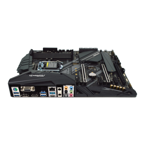
Summary of Contents for ASROCK Z930 EXTREME4
- Page 2 (including damages for loss of profits, loss of business, loss of data, interruption of business and the like), even if ASRock has been advised of the possibility of such damages arising from any defect or error in the documentation or product.
- Page 3 You are also entitled to have the goods repaired or replaced if the goods fail to be of acceptable quality and the failure does not amount to a major failure. If you require assistance please call ASRock Tel : +886-2-28965588 ext.123 (Standard International call charges apply) The terms HDMI®...
-
Page 4: Table Of Contents
Contents Chapter 1 Introduction Package Contents Specifications Motherboard Layout I/O Panel Chapter 2 Installation Installing the CPU Installing the CPU Fan and Heatsink Installing Memory Modules (DIMM) Expansion Slots (PCI Express Slots) Jumpers Setup Onboard Headers and Connectors and Quad SLI Operation Guide 2.7.1 Installing Two SLI -Ready Graphics Cards... - Page 5 Chapter 3 Software and Utilities Operation Installing Drivers A-Tuning 3.2.1 Installing A-Tuning 3.2.2 Using A-Tuning ASRock Live Update & APP Shop 3.3.1 UI Overview 3.3.2 Apps 3.3.3 BIOS & Drivers 3.3.4 Setting ASRock Polychrome RGB Chapter 4 UEFI SETUP UTILITY...
- Page 6 4.6.5 Super IO Configuration 4.6.6 ACPI Configuration 4.6.7 USB Configuration 4.6.8 Trusted Computing Tools Hardware Health Event Monitoring Screen Security Screen 4.10 Boot Screen 4.11 Exit Screen...
-
Page 7: Chapter 1 Introduction
If you require technical support related to this mother- board, please visit our website for specific information about the model you are using. You may find the latest VGA cards and CPU support list on ASRock’s website as well. ASRock website http://www.asrock.com. -
Page 8: Specifications
• Supports DDR4 4300+(OC)*/4266(OC)/4133(OC)/4000 (OC)/3866(OC)/3800(OC)/3733(OC)/3600(OC)/3200(OC)/ 2933(OC)/2800(OC)/2666/2400/2133 non-ECC, un-buffered memory * Please refer to Memory Support List on ASRock's website for more information. (http://www.asrock.com/) • Supports ECC UDIMM memory modules (operate in non- ECC mode) • Max. capacity of system memory: 64GB • Supports Intel®... - Page 9 Z390 Extreme4 Graphics • Intel® UHD Graphics Built-in Visuals and the VGA outputs can be supported only with processors which are GPU integrated. • Supports Intel® UHD Graphics Built-in Visuals : Intel® Quick Sync Video with AVC, MVC (S3D) and MPEG-2 Full HW Encode1, Intel®...
- Page 10 - Direct Drive Technology - PCB Isolate Shielding - Impedance Sensing on Rear Out port - Individual PCB Layers for R/L Audio Channel - RGB LED - 15μ Gold Audio Connector • Supports DTS Connect • Gigabit LAN 10/100/1000 Mb/s • Giga PHY Intel®...
- Page 11 M.2 PCI Express module up to Gen3 x4 (32 Gb/s)** ** Supports Intel® Optane Technology ** Supports NVMe SSD as boot disks ** Supports ASRock U.2 Kit Connector • 1 x COM Port Header • 1 x TPM Header • 1 x Power LED and Speaker Header...
- Page 12 • 1 x 4 pin 12V Power Connector (Hi-Density Power Connector) • 1 x Front Panel Audio Connector (15μ Gold Audio Connector) • 1 x Thunderbolt AIC Connector (5-pin) • 2 x USB 2.0 Headers (Support 4 USB 2.0 ports) (Intel® Z390) (Supports ESD Protection) • 2 x USB 3.1 Gen1 Headers (Support 4 USB 3.1 Gen1 ports) (ASMedia ASM1074 hub) (Supports ESD Protection)
- Page 13 Z390 Extreme4 * For detailed product information, please visit our website: http://www.asrock.com Please realize that there is a certain risk involved with overclocking, including adjusting the setting in the BIOS, applying Untied Overclocking Technology, or using third-party overclocking tools. Overclocking may affect your system’s stability, or even cause damage to the components and devices of your system.
-
Page 14: Motherboard Layout
1.3 Motherboard Layout CPU_FAN1 ATX12V1 ATX12V2 CPU_FAN2/WP USB 3.1 Gen1 T: USB3 B: USB4 USB 3.1 Gen2 Top: T: USB31_TA_1 RJ-45 B: USB31_TC_1 Ultra M.2 Z390 EXTREME4 PCIe Gen3 x4 CHA_FAN1/WP USB31_TC_2 PCIE1 RoHS PCIE2 Intel CMOS Battery Z390 CLRMOS1 Purity PCIE3 Sound 4... - Page 15 Z390 Extreme4 No. Description 8 pin 12V Power Connector (ATX12V1) 4 pin 12V Power Connector (ATX12V2) CPU Fan Connector (CPU_FAN1) CPU/Water Pump Fan Connector (CPU_FAN2/WP) 2 x 288-pin DDR4 DIMM Slots (DDR4_A1, DDR4_B1) 2 x 288-pin DDR4 DIMM Slots (DDR4_A2, DDR4_B2) ATX Power Connector (ATXPWR1) USB 3.1 Gen1 Header (USB3_5_6) USB 3.1 Gen1 Header (USB3_7_8)
-
Page 16: I/O Panel
1.4 I/O Panel No. Description No. Description PS/2 Mouse/Keyboard Port Optical SPDIF Out Port D-Sub Port Antenna Ports LAN RJ-45 Port* USB 3.1 Gen2 Type-A Port (USB31_TA_1) Central / Bass (Orange) USB 3.1 Gen2 Type-C Port (USB31_TC_1) Rear Speaker (Black) USB 3.1 Gen1 Ports (USB3_34) Line In (Light Blue) HDMI Port... - Page 17 Z390 Extreme4 * There are two LEDs on each LAN port. Please refer to the table below for the LAN port LED indications. ACT/LINK LED SPEED LED LAN Port Activity / Link LED Speed LED Status Description Status Description No Link 10Mbps connection Blinking Data Activity...
-
Page 18: Chapter 2 Installation
Chapter 2 Installation This is an ATX form factor motherboard. Before you install the motherboard, study the configuration of your chassis to ensure that the motherboard fits into it. Pre-installation Precautions Take note of the following precautions before you install motherboard components or change any motherboard settings. -
Page 19: Installing The Cpu
Z390 Extreme4 2.1 Installing the CPU 1. Before you insert the 1151-Pin CPU into the socket, please check if the PnP cap is on the socket, if the CPU surface is unclean, or if there are any bent pins in the socket. Do not force to insert the CPU into the socket if above situation is found. - Page 21 Z390 Extreme4 Please save and replace the cover if the processor is removed. The cover must be placed if you wish to return the motherboard for after service.
-
Page 22: Installing The Cpu Fan And Heatsink
2.2 Installing the CPU Fan and Heatsink... -
Page 23: Installing Memory Modules (Dimm)
Z390 Extreme4 2.3 Installing Memory Modules (DIMM) This motherboard provides four 288-pin DDR4 (Double Data Rate 4) DIMM slots, and supports Dual Channel Memory Technology. 1. For dual channel configuration, you always need to install identical (the same brand, speed, size and chip-type) DDR4 DIMM pairs. 2. -
Page 25: Expansion Slots (Pci Express Slots)
Z390 Extreme4 2.4 Expansion Slots (PCI Express Slots) There are 6 PCI Express slots on the motherboard. Before installing an expansion card, please make sure that the power supply is switched off or the power cord is unplugged. Please read the documentation of the expansion card and make necessary hardware settings for the card before you start the installation. -
Page 26: Jumpers Setup
2.5 Jumpers Setup The illustration shows how jumpers are setup. When the jumper cap is placed on the pins, the jumper is “Short”. If no jumper cap is placed on the pins, the jumper is “Open”. Clear CMOS Jumper Short: Clear CMOS (CLRCMOS1) Open: Default 2-pin Jumper... -
Page 27: Onboard Headers And Connectors
Z390 Extreme4 2.6 Onboard Headers and Connectors Onboard headers and connectors are NOT jumpers. Do NOT place jumper caps over these headers and connectors. Placing jumper caps over the headers and connectors will cause permanent damage to the motherboard. System Panel Header Connect the power PLED+ PLED-... - Page 28 Power LED and Speaker Please connect the SPEAKER DUMMY Header chassis power LED and DUMMY (7-pin SPK_PLED1) the chassis speaker to this (see p.8, No. 18) header. PLED+ PLED+ PLED- Serial ATA3 Connectors These eight SATA3 (SATA3_4_5: connectors support SATA see p.8, No.
- Page 29 Z390 Extreme4 USB 3.1 Gen1 Headers There are two headers on Vbus Vbus Vbus IntA_PB_SSRX- (19-pin USB3_5_6) this motherboard. Each IntA_PB_SSRX+ IntA_PA_SSRX- IntA_PA_SSRX+ (see p.8, No. 8) USB 3.1 Gen1 header can IntA_PB_SSTX- IntA_PA_SSTX- IntA_PB_SSTX+ (19-pin USB3_7_8) support two ports. IntA_PA_SSTX+ IntA_PB_D- (see p.8, No.
- Page 30 Chassis/Water Pump Fan This motherboard FAN_VOLTAGE Connectors provides three 4-Pin water FAN_SPEED FAN_SPEED_CONTROL (4-pin CHA_FAN1/WP) cooling chassis fan (see p.8, No. 30) connectors. If you plan to connect a 3-Pin chassis water cooler fan, please (4-pin CHA_FAN2/WP) connect it to Pin 1-3. FAN_VOLTAGE FAN_SPEED (see p.8, No.
- Page 31 Z390 Extreme4 ATX 12V Power This motherboard Connector provides an 8-pin ATX (8-pin ATX12V1) 12V power connector. To (see p.8, No. 1) use a 4-pin ATX power supply, please plug it along Pin 1 and Pin 5. ATX 12V Power Please connect an ATX Connector 12V power supply to this...
- Page 32 RGB LED Headers RGB header is used to connect (4-pin RGB_LED1) RGB LED extension cable which 12V G R (see p.8, No. 26) allows users to choose from vari- (4-pin RGB_LED2) ous LED lighting effects. (see p.8, No. 25) Caution: Never install the RGB LED cable in the wrong orienta- tion;...
-
Page 33: Sli Tm And Quad Sli
Z390 Extreme4 2.7 SLI and Quad SLI Operation Guide ® This motherboard supports NVIDIA and Quad SLI (Scalable Link Interface) technology that allows you to install up to two identical PCI Express x16 graphics cards. Requirements ® 1. You should only use identical SLI -ready graphics cards that are NVIDIA certified. - Page 34 Step 3 Align and insert the ASRock SLI_HB_ Bridge_2S Card to the goldfingers on each graphics card. Make sure the ASRock SLI_ HB_Bridge_2S Card is firmly in place. SLI_HB_Bridge_2S Car d ASRock SLI_HB_Bridge_2S Card Step 4 Connect a VGA cable or a DVI cable to the...
-
Page 35: Driver Installation And Setup
Z390 Extreme4 2.7.2 Driver Installation and Setup Install the graphics card drivers to your system. After that, you can enable the ® Multi-Graphics Processing Unit (GPU) in the NVIDIA nView system tray utility. Please follow the below procedures to enable the multi-GPU. For SLI and Quad SLI mode... -
Page 36: Tm Tm Tm
2.8 CrossFireX , 3-Way CrossFireX and Quad CrossFireX Operation Guide This motherboard supports CrossFireX , 3-way CrossFireX and Quad CrossFireX that allows you to install up to three identical PCI Express x16 graphics cards. 1. You should only use identical CrossFireX -ready graphics cards that are AMD certified. - Page 37 Z390 Extreme4 Step 3 Connect a VGA cable or a DVI cable to the monitor connector or the DVI connec- tor of the graphics card that is inserted to PCIE2 slot.
-
Page 38: Installing Three Crossfirex
2.8.2 Installing Three CrossFireX -Ready Graphics Cards Step 1 Insert one graphics card into PCIE2 slot, another graphics card to PCIE4 slot, and the other graphics card to PCIE6 slot. Make sure that the cards are properly seated on the slots. Step 2 Use one CrossFire Bridge to connect the graphics cards on PCIE2 and PCIE4... -
Page 39: Driver Installation And Setup
Z390 Extreme4 2.8.3 Driver Installation and Setup Step 1 Power on your computer and boot into OS. Step 2 Remove the AMD drivers if you have any VGA drivers installed in your system. The Catalyst Uninstaller is an optional download. We recommend using this utility to un- install any previously installed Catalyst drivers prior to installation. -
Page 40: Wifi/Bt Module And Intel® Cnvi (Integrated Wifi/Bt) Installation Guide
2.9 M.2 WiFi/BT Module and Intel® CNVi (Integrated WiFi/BT) Installation Guide The M.2, also known as the Next Generation Form Factor (NGFF), is a small size and versatile card edge connector that aims to replace mPCIe and mSATA. The M.2 Socket (Key E) supports type 2230 WiFi/BT module and Intel®... - Page 41 Z390 Extreme4 Step 3 Gently insert the WiFi/BT module or Intel® CNVi (Integrated WiFi/ BT) into the M.2 slot. Please be aware that the module only fits in one orientation. Step 4 Tighten the screw with a screwdriver to secure the module into place. Please do not overtighten the screw as this might damage the module.
-
Page 42: M.2_Ssd (Ngff) Module Installation Guide
2.10 M.2_SSD (NGFF) Module Installation Guide (M2_1 and M2_2) The M.2, also known as the Next Generation Form Factor (NGFF), is a small size and versatile card edge connector that aims to replace mPCIe and mSATA. The Ultra M.2 Sockets (M2_1 and M2_2) support SATA3 6.0 Gb/s module and M.2 PCI Express module up to Gen3 x4 (32 Gb/s). - Page 43 Z390 Extreme4 Step 3 Before installing a M.2 (NGFF) SSD module, please loosen the screws to remove the M.2 heatsink. Step4 Align and gently insert the M.2 (NGFF) SSD module into the M.2 slot. Please be aware that the M.2 (NGFF) SSD module only fits in one orientation.
- Page 44 M.2_SSD (NGFF) Module Support List Vendor Interface ADATA SATA3 AXNS330E-32GM-B ADATA SATA3 AXNS381E-128GM-B ADATA SATA3 AXNS381E-256GM-B ADATA SATA3 ASU800NS38-256GT-C ADATA SATA3 ASU800NS38-512GT-C ADATA PCIe3 x4 ASX7000NP-128GT-C ADATA PCIe3 x4 ASX8000NP-256GM-C ADATA PCIe3 x4 ASX7000NP-256GT-C ADATA PCIe3 x4 ASX8000NP-512GM-C ADATA PCIe3 x4 ASX7000NP-512GT-C Apacer PCIe3 x4...
- Page 45 SATA3 VLM100-120G-2280B-RD V-Color SATA3 VLM100-240G-2280RGB V-Color SATA3 VSM100-240G-2280 V-Color SATA3 VLM100-240G-2280B-RD SATA3 WDS100T1B0B-00AS40 SATA3 WDS240G1G0B-00RC30 PCIe3 x4 WDS256G1X0C-00ENX0 (NVME) PCIe3 x4 WDS512G1X0C-00ENX0 (NVME) For the latest updates of M.2_SSD (NFGG) module support list, please visit our website for details: http://www.asrock.com...
-
Page 46: Chapter 3 Software And Utilities Operation
Chapter 3 Software and Utilities Operation 3.1 Installing Drivers The Support CD that comes with the motherboard contains necessary drivers and useful utilities that enhance the motherboard’s features. Running The Support CD To begin using the support CD, insert the CD into your CD-ROM drive. The CD automatically displays the Main Menu if “AUTORUN”... -
Page 47: A-Tuning
Z390 Extreme4 3.2 A-Tuning A-Tuning is ASRock’s multi purpose software suite with a new interface, more new features and improved utilities. 3.2.1 Installing A-Tuning A-Tuning can be downloaded from ASRock Live Update & APP Shop. After the installation, you will find the icon “A-Tuning“ on your desktop. Double-click the “A-Tuning“... - Page 48 OC Tweaker Configurations for overclocking the system. System Info View information about the system. *The System Browser tab may not appear for certain models.
- Page 49 Configure up to five different fan speeds using the graph. The fans will automatically shift to the next speed level when the assigned temperature is met. Settings Configure ASRock A-Tuning. Click to select "Auto run at Windows Startup" if you want A-Tuning to be launched when you start up the Windows operating system.
-
Page 50: Asrock Live Update & App Shop
Double-click on your desktop to access ASRock Live Update & APP Shop utility. *You need to be connected to the Internet to download apps from the ASRock Live Update & APP Shop. 3.3.1 UI Overview Category Panel Hot News... -
Page 51: Apps
Z390 Extreme4 3.3.2 Apps When the "Apps" tab is selected, you will see all the available apps on screen for you to download. Installing an App Step 1 Find the app you want to install. The most recommended app appears on the left side of the screen. The other various apps are shown on the right. - Page 52 Step 3 If you want to install the app, click on the red icon to start downloading. Step 4 When installation completes, you can find the green "Installed" icon appears on the upper right corner. To uninstall it, simply click on the trash can icon *The trash icon may not appear for certain apps.
- Page 53 Z390 Extreme4 Upgrading an App You can only upgrade the apps you have already installed. When there is an available new version for your app, you will find the mark of "New Version" appears below the installed app icon. Step 1 Click on the app icon to see more details.
-
Page 54: Bios & Drivers
3.3.3 BIOS & Drivers Installing BIOS or Drivers When the "BIOS & Drivers" tab is selected, you will see a list of recommended or critical updates for the BIOS or drivers. Please update them all soon. Step 1 Please check the item information before update. Click on to see more details. -
Page 55: Setting
Z390 Extreme4 3.3.4 Setting In the "Setting" page, you can change the language, select the server location, and determine if you want to automatically run the ASRock Live Update & APP Shop on Windows startup. -
Page 56: Asrock Polychrome Rgb
3.5 ASRock Polychrome RGB ASRock Polychrome RGB is a lighting control utility specifically designed for unique individuals with sophisticated tastes to build their own stylish colorful lighting system. Simply by connect- ing the LED strip, you can customize various lighting schemes and patterns, including Static, Breathing, Strobe, Cycling, Music, Wave and more. - Page 57 Z390 Extreme4 Connecting the Addressable RGB LED Strip Connect your Addressable RGB LED strip to the Addressable LED Header (ADDR_LED1) on the motherboard. ADDR_LED1 DO_ADDR VOUT Z390 EXTREME4 1. Never install the RGB LED cable in the wrong orientation; otherwise, the cable may be damaged.
- Page 58 ASRock Polychrome RGB Utility Now you can adjust the RGB LED color through the ASRock Polychrome RGB Utility. Download this utility from the ASRock Live Update & APP Shop and start coloring your PC style your way! Drag the tab to customize your preference.
-
Page 59: Chapter 4 Uefi Setup Utility
Z390 Extreme4 Chapter 4 UEFI SETUP UTILITY 4.1 Introduction This section explains how to use the UEFI SETUP UTILITY to configure your system. You may run the UEFI SETUP UTILITY by pressing <F2> or <Del> right after you power on the computer, otherwise, the Power-On-Self-Test (POST) will continue with its test routines. -
Page 60: Ez Mode
4.2 EZ Mode The EZ Mode screen appears when you enter the BIOS setup program by default. EZ mode is a dashboard which contains multiple readings of the system’s current status. You can check the most crucial information of your system, such as CPU speed, DRAM frequency, SATA information, fan speed, etc. -
Page 61: Advanced Mode
Z390 Extreme4 4.3 Advanced Mode The Advanced Mode provides more options to configure the BIOS settings. Refer to the following sections for the detailed configurations. To access the EZ Mode, press <F6> or click the "EZ Mode" button at the upper right corner of the screen. -
Page 62: Navigation Keys
4.3.2 Navigation Keys Use < > key or < > key to choose among the selections on the menu bar, and use < > key or < > key to move the cursor up or down to select items, then press <Enter>... -
Page 63: Main Screen
Z390 Extreme4 4.4 Main Screen When you enter the UEFI SETUP UTILITY, the Main screen will appear and display the system overview. My Favorite Display your collection of BIOS items. Press F5 to add/remove your favorite items. -
Page 64: Oc Tweaker Screen
4.5 OC Tweaker Screen In the OC Tweaker screen, you can set up overclocking features. Because the UEFI software is constantly being updated, the following UEFI setup screens and descriptions are for reference purpose only, and they may not exactly match what you see on your screen. - Page 65 Z390 Extreme4 CPU Configuration Performance mode Intel Performance Mode allows you to do real-time overclocking by pressing the OC button. The OC LED reminds you the Performance mode is ON. Please select the overclocking rule for Performance mode. [Disabled] Select this item to disable Intel Performance Mode. [CPU Ratio +1] , [CPU Ratio +2] and [CPU Ratio +3] Select the level of overclocking performed.
- Page 66 Boot Performance Mode Default is Max Non-Turbo performance mode. It will keep cpu Flex-ratio till OS handoff. Max Battery mode will set CPU ratio as x8 till OS handoff. This option is suggested for BCLK overclocking. FCLK Frequency Configure the FCLK Frequency. AVX Ratio Offset AVX Ratio Offset specifies a negative offset from the CPU Ratio for AVX workloads.
- Page 67 Z390 Extreme4 Intel Speed Shift Technology Enable/Disable Intel Speed Shift Technology support. Enabling will expose the CPPC v2 interface to allow for hardware controlled P-sates. Long Duration Power Limit Configure Package Power Limit 1 in watts. When the limit is exceeded, the CPU ratio will be lowered after a period of time.
- Page 68 Primary Timing CAS# Latency (tCL) The time between sending a column address to the memory and the beginning of the data in response. RAS# to CAS# Delay and Row Precharge (tRCDtRP) RAS# to CAS# Delay : The number of clock cycles required between the opening of a row of memory and accessing columns within it.
- Page 69 Z390 Extreme4 the same internal bank. Write to Read Delay (tWTR_S) The number of clocks between the last valid write operation and the next read command to the same internal bank. Read to Precharge (tRTP) The number of clocks that are inserted between a read command to a row pre- charge command to the same rank.
- Page 70 tRDWR_dg Configure between module read to write delay. tRDWR_dr Configure between module read to write delay. tRDWR_dd Configure between module read to write delay. tWRRD_sg Configure between module write to read delay. tWRRD_dg Configure between module write to read delay. tWRRD_dr Configure between module write to read delay.
- Page 71 Z390 Extreme4 RTL (CH A) Configure round trip latency for channel A. RTL (CH B) Configure round trip latency for channel B. IO-L (CH A) Configure IO latency for channel A. IO-L (CH B) Configure IO latency for channel B. IOL Offset (CH A) Configure IO latency offset for channel A.
- Page 72 ODT NOM (A2) Use this to change ODT (CH A2) Auto/Manual settings. The default is [Auto]. ODT NOM (B1) Use this to change ODT (CH B1) Auto/Manual settings. The default is [Auto]. ODT NOM (B2) Use this to change ODT (CH B2) Auto/Manual settings. The default is [Auto]. ODT PARK (A1) Configure the memory on die termination resistors' PARK for channel A1.
- Page 73 Configure the tCWL for Memory MRS MR2. MRS tCCD_L Configure the tCL for Memory MRS MR6. Advanced Setting ASRock Timing Optimization Configure the fast path through the MRC. Realtime Memory Timing Configure the realtime memory timings. [Enabled] The system will allow performing realtime memory timing changes after...
- Page 74 Command Tristate Configure the Command Tristate Support. Exit On Failure Configure the Exit On Failure for MRC training steps. Reset On Training Fail Reset system if the MRC training fails. MRC Fast Boot Enable Memory Fast Boot to skip DRAM memory training for booting faster. Voltage Configuration CPU Core/Cache Voltage Configure the voltage for the CPU Core/Cache.
- Page 75 Z390 Extreme4 VCCST Voltage Configure the voltage for the VCCST. VCCSA Voltage Configure the voltage for the VCCSA. VCCPLL Voltage Configure the voltage for the VCCPLL. Save User Default Type a profile name and press enter to save your settings as user default. Load User Default Load previously saved user defaults.
-
Page 76: Advanced Screen
4.6 Advanced Screen In this section, you may set the configurations for the following items: CPU Configuration, Chipset Configuration, Storage Configuration, Intel(R) Thunder- bolt, Super IO Configuration, ACPI Configuration, USB Configuration and Trusted Computing. Setting wrong values in this section may cause the system to malfunction. UEFI Configuration UEFI Setup Style Select the default mode when entering the UEFI setup utility. -
Page 77: Cpu Configuration
Z390 Extreme4 4.6.1 CPU Configuration Intel Hyper Threading Technology Intel Hyper Threading Technology allows multiple threads to run on each core, so that the overall performance on threaded software is improved Active Processor Cores Select the number of cores to enable in each processor package. CPU C States Support Enable CPU C States Support for power saving. - Page 78 CPU C7 State Support Enable C7 sleep state for lower power consumption. CPU C10 State Support Enable C10 sleep state for lower power consumption. Package C State Support Enable CPU, PCIe, Memory, Graphics C State Support for power saving. CFG Lock This item allows you to disable or enable the CFG Lock.
-
Page 79: Chipset Configuration
Z390 Extreme4 4.6.2 Chipset Configuration Primary Graphics Adapter Select a primary VGA. Above 4G Decoding Enable or disable 64bit capable Devices to be decoded in Above 4G Address Space (only if the system supports 64 bit PCI decoding). VT-d Intel® Virtualization Technology for Directed I/O helps your virtual machine monitor better utilize hardware by improving application compatibility and reliability, and providing additional levels of manageability, security, isolation, and I/O performance. - Page 80 PCIE4 Link Speed Select the link speed for PCIE4. PCIE5 Link Speed Select the link speed for PCIE5. PCIE6 Link Speed Select the link speed for PCIE6. PCI Express Native Control Select Enable for enhanced PCI Express power saving in OS. PCIE ASPM Support This option enables/disables the ASPM support for all CPU downstream devices.
- Page 81 Z390 Extreme4 Front Panel Enable/disable front panel HD audio. Onboard HDMI HD Audio Enable audio for the onboard digital outputs. Deep Sleep Configure deep sleep mode for power saving when the computer is shut down. Restore on AC/Power Loss Select the power state after a power failure. If [Power Off] is selected, the power will remain off when the power recovers.
-
Page 82: Storage Configuration
4.6.3 Storage Configuration SATA Controller(s) Enable/disable the SATA controllers. SATA Mode Selection [AHCI] Supports new features that improve performance. [Intel RST Premium (RAID)] Combine multiple disk drives into a logical unit. SATA Aggressive Link Power Management SATA Aggressive Link Power Management allows SATA devices to enter a low power state during periods of inactivity to save power. - Page 83 Z390 Extreme4 Third Party SATA3 Mode [AHCI] Supports new features that improve performance.
-
Page 84: Intel® Thunderbolt
4.6.4 Intel® Thunderbolt Discrete Thunderbolt(TM) Support Enable or disable the Discrete Thunderbolt(TM) Support. Thunderbolt Boot Support Enabled to allow booting from Bootable devices which are present behind Thunderbolt. Thunderbolt Usb Support Enabled to allow booting from Usb devices which are present behind Thunderbolt. Titan Ridge Workaround for OSUP Enable or disable Titan Ridge Workaround for OSUP. - Page 85 Z390 Extreme4 Windows 10 Thunderbolt support Specify Windows 10 Thunderbolt support level. Disabled: No OS native support. Enabled: OS Native support only. no RTD3.
-
Page 86: Super Io Configuration
4.6.5 Super IO Configuration Serial Port Enable or disable the Serial port. Serial Port Address Select the address of the Serial port. PS2 Y-Cable Enable the PS2 Y-Cable or set this option to Auto. -
Page 87: Acpi Configuration
Z390 Extreme4 4.6.6 ACPI Configuration Suspend to RAM Select disable for ACPI suspend type S1. It is recommended to select auto for ACPI S3 power saving. PS/2 Keyboard S4/S5 Wakeup Support Allow the system to be waked up by a PS/2 Keyboard in S4/S5. PCIE Devices Power On Allow the system to be waked up by a PCIE device and enable wake on LAN. - Page 88 USB Mouse Power On Allow the system to be waked up by an USB mouse.
-
Page 89: Usb Configuration
Z390 Extreme4 4.6.7 USB Configuration Legacy USB Support Enable or disable Legacy OS Support for USB 2.0 devices. If you encounter USB compatibility issues it is recommended to disable legacy USB support. Select UEFI Setup Only to support USB devices under the UEFI setup and Windows/Linux operating systems only. -
Page 90: Trusted Computing
4.6.8 Trusted Computing Security Device Support Enable or disable BIOS support for security device. -
Page 91: Tools
Z390 Extreme4 4.7 Tools UEFI Tech Service Contact ASRock Tech Service if you are having trouble with your PC. Please setup network configuration before using UEFI Tech Service. Easy RAID Installer Easy RAID Installer helps you to copy the RAID driver from the support CD to your USB storage device. - Page 92 Secure Backup UEFI Whenever one of the ROM images are outdated or corrupted, switch to the other flash ROM and execute Secure Backup UEFI to duplicate the current working ROM image to the secondary flash ROM. This motherboard has two BIOS chips, an active BIOS (BIOS_A) and a backup BIOS (BIOS_B), which enhances the safety and stability of your system.
-
Page 93: Hardware Health Event Monitoring Screen
Z390 Extreme4 4.8 Hardware Health Event Monitoring Screen This section allows you to monitor the status of the hardware on your system, including the parameters of the CPU temperature, motherboard temperature, fan speed and voltage. Fan Tuning Measure Fan Min Duty Cycle. Fan-Tastic Tuning Select a fan mode for CPU Fans 1&2, or choose Customize to set 5 CPU temperatures and assign a respective fan speed for each temperature. - Page 94 CPU_FAN2 / W _ Pump Switch Select CPU or Water Pump mode. CPU_FAN2 Control Mode Select PWM mode or DC mode for CPU_FAN2. CPU_FAN2 Setting Select a fan mode for CPU_FAN2, or choose Customize to set 5 CPU temperatures and assign a respective fan speed for each temperature. CPU_FAN2 Temp Source Select a fan temperature source for CPU_FAN2.
- Page 95 Z390 Extreme4 CHA_FAN2 Setting Select a fan mode for CHA_FAN2, or choose Customize to set 5 CPU temperatures and assign a respective fan speed for each temperature. Chassis Fan 2 Temp Source Select a fan temperature source for Chassis Fan 2. Chassis Fan 2 Step Up Set the value of Chassis Fan 2 Step Up.
-
Page 96: Security Screen
4.9 Security Screen In this section you may set or change the supervisor/user password for the system. You may also clear the user password. Supervisor Password Set or change the password for the administrator account. Only the administrator has authority to change the settings in the UEFI Setup Utility. Leave it blank and press enter to remove the password. -
Page 97: Boot Screen
Z390 Extreme4 4.10 Boot Screen This section displays the available devices on your system for you to configure the boot settings and the boot priority. Fast Boot Fast Boot minimizes your computer's boot time. In fast mode you may not boot from an USB storage device. - Page 98 Full Screen Logo Enable to display the boot logo or disable to show normal POST messages. AddOn ROM Display Enable AddOn ROM Display to see the AddOn ROM messages or configure the AddOn ROM if you've enabled Full Screen Logo. Disable for faster boot speed. Boot Failure Message If the computer fails to boot for a number of times the system automatically restores the default settings.
- Page 99 Z390 Extreme4 Launch Storage OpROM Policy Select UEFI only to run those that support UEFI option ROM only. Select Legacy only to run those that support legacy option ROM only. Select Do not launch to not execute both legacy and UEFI option ROM. Other PCI Device ROM Priority For PCI devices other than Network.
-
Page 100: Exit Screen
4.11 Exit Screen Save Changes and Exit When you select this option the following message, “Save configuration changes and exit setup?” will pop out. Select [OK] to save changes and exit the UEFI SETUP UTILITY. Discard Changes and Exit When you select this option the following message, “Discard changes and exit setup?”... - Page 101 Contact Information If you need to contact ASRock or want to know more about ASRock, you’re welcome to visit ASRock’s website at http://www.asrock.com; or you may contact your dealer for further information. For technical questions, please submit a support request form at http://www.asrock.com/support/tsd.asp...
- Page 102 DECLARATION OF CONFORMITY Per FCC Part 2 Section 2.1077(a) Responsible Party Name: ASRock Incorporation 13848 Magnolia Ave, Chino, CA91710 Address: Phone/Fax No: +1-909-590-8308/+1-909-590-1026 hereby declares that the product Product Name : Motherboard Z390 Extreme4 Model Number : Conforms to the following speci cations:...
- Page 103 EU Declaration of Conformity For the following equipment: Motherboard (Product Name) Z390 Extreme4 / ASRock (Model Designation / Trade Name) ASRock Incorporation (Manufacturer Name) 2F., No.37, Sec. 2, Jhongyang S. Rd., Beitou District, Taipei City 112, Taiwan (R.O.C.) (Manufacturer Address) EMC —Directive 2014/30/EU (from April 20th, 2016)
Need help?
Do you have a question about the Z930 EXTREME4 and is the answer not in the manual?
Questions and answers