Table of Contents
Advertisement
Advertisement
Table of Contents

Related Manuals for ASROCK Z97 Extreme4


Summary of Contents for ASROCK Z97 Extreme4
-
Page 2: Copyright Notice
(including damages for loss of profits, loss of business, loss of data, interruption of business and the like), even if ASRock has been advised of the possibility of such damages arising from any defect or error in the documentation or product. - Page 3 The terms HDMI™ and HDMI High-Definition Multimedia Interface, and the HDMI logo are trademarks or registered trademarks of HDMI Licensing LLC in the United States and other countries. Manufactured under license under U.S. Patent Nos: 5,956,674; 5,974,380; 6,487,535; 7,003,467 & other U.S. and worldwide patents issued & pending. DTS, the Symbol, & DTS and the Symbol together is a registered trademark &...
-
Page 4: Table Of Contents
Contents Chapter 1 Introduction Package Contents Specifications Motherboard Layout I/O Panel Chapter 2 Installation Installing the CPU Installing the CPU Fan and Heatsink Installing Memory Modules (DIMM) Expansion Slots (PCI Express Slots) Jumpers Setup Onboard Headers and Connectors Smart Switches Dr. - Page 5 3.4.1 System Requirements 3.4.2 Setup Guide ASRock Cloud 3.5.1 Intel® Remote Wake Technology 3.5.2 Configuring and Using Orbweb.ME Professional 3.5.3 Remote Access from a Client Device ASRock APP Shop 3.6.1 UI Overview 3.6.2 Apps 3.6.3 BIOS & Drivers 3.6.4 Setting Start8 3.7.1...
- Page 6 Chapter 4 UEFI SETUP UTILITY Introduction 4.1.1 UEFI Menu Bar 4.1.2 Navigation Keys Main Screen OC Tweaker Screen Advanced Screen 4.4.1 CPU Configuration 4.4.2 Chipset Configuration 4.4.3 Storage Configuration 4.4.4 Intel® Rapid Start Technology 4.4.5 Intel® Smart Connect Technology 4.4.6 Super IO Configuration 4.4.7 ACPI Configuration 4.4.8 USB Configuration Tools...
-
Page 7: Chapter 1 Introduction
If you require technical support related to this mother- board, please visit our website for specific information about the model you are using. You may find the latest VGA cards and CPU support list on ASRock’s website as well. ASRock website http://www.asrock.com. -
Page 8: Specifications
Core™ i7/i5/i3/Pentium®/Celeron® Processors (Socket 1150) • Digi Power design • 12 Power Phase design • Supports Intel® Turbo Boost 2.0 Technology • Supports Intel® K-Series unlocked CPUs • Supports ASRock BCLK Full-range Overclocking Chipset • Intel® Z97 Memory • Dual Channel DDR3 Memory Technology • 4 x DDR3 DIMM Slots... - Page 9 • 7.1 CH HD Audio with Content Protection (Realtek ALC1150 Audio Codec) • Premium Blu-ray Audio support • Supports Surge Protection (ASRock Full Spike Protection) • Supports Purity Sound - Nichicon Fine Gold Series Audio Caps - 115dB SNR DAC with Differential Amplifier - TI®...
- Page 10 • 1 x HDMI Port • 1 x DisplayPort 1.2 • 1 x Optical SPDIF Out Port • 2 x USB 2.0 Ports (Supports ESD Protection (ASRock Full Spike Protection)) • 2 x USB 3.0 Ports (ASMedia ASM1042AE) (Supports ESD Protection (ASRock Full Spike Protection)) • 4 x USB 3.0 Ports (Intel®...
- Page 11 • 1 x Front Panel Audio Connector • 2 x USB 2.0 Headers (support 4 USB 2.0 ports) (Supports ESD Protection (ASRock Full Spike Protection)) • 1 x USB 3.0 Header (support 2 USB 3.0 ports) (Supports ESD Protection (ASRock Full Spike Protection)) • 1 x Dr.
- Page 12 Due to limitation, the actual memory size may be less than 4GB for the reservation for sys- tem usage under Windows® 32-bit operating systems. Windows® 64-bit operating systems do not have such limitations. You can use ASRock XFast RAM to utilize the memory that Windows® cannot use.
-
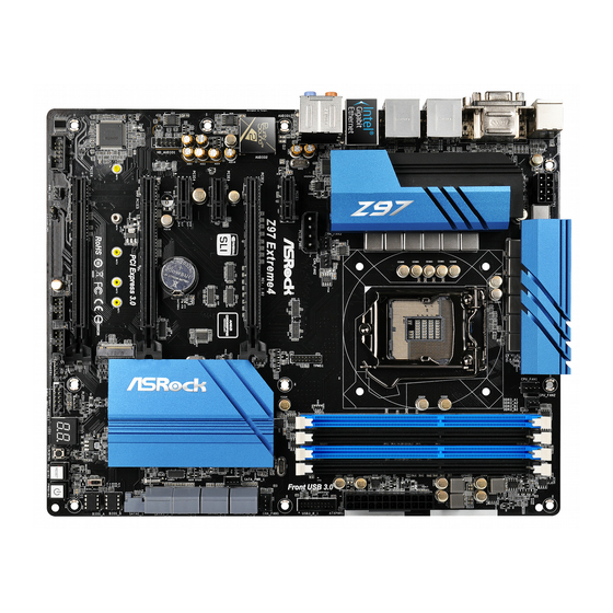
Page 13: Motherboard Layout
Z97 Extreme4 1.3 Motherboard Layout ATX12V1 CPU_FAN2 CPU_FAN1 USB 3.0 Top: T: USB6 RJ-45 B: USB7 CHA_FAN3 CHA_FAN2 PCIE_PWR1 TPMS1 PCIE1 Z97 Extreme4 Purity CHA_FAN1 Sound PCIE2 SATA_PWR_1 PCIE3 Intel PCIE4 CMOS Battery HD_AUDIO1 PCIE5 PCI Express 3.0 64Mb NUT5... - Page 14 No. Description ATX 12V Power Connector (ATX12V1) CPU Fan Connector (CPU_FAN1) CPU Fan Connector (CPU_FAN2) 2 x 240-pin DDR3 DIMM Slots (DDR3_A1, DDR3_B1) 2 x 240-pin DDR3 DIMM Slots (DDR3_A2, DDR3_B2) ATX Power Connector (ATXPWR1) USB 3.0 Header (USB3_0_1) HDD Saver Connector (SATA_PWR_1) Chassis Fan Connector (CHA_FAN1) SATA3 Connector (SATA3_A0) SATA3 Connector (SATA3_A1)
- Page 15 Z97 Extreme4 No. Description Chassis Fan Connector (CHA_FAN3) Chassis Fan Connector (CHA_FAN2)
-
Page 16: I/O Panel
1.4 I/O Panel No. Description No. Description USB 2.0 Ports (USB01) Microphone (Pink) D-Sub Port Optical SPDIF Out Port USB 3.0 Ports (USB3_45) (Intel® Z97) USB 3.0 Ports (USB3_67) USB 3.0 Ports (USB3_23) (Intel® Z97) (ASMedia ASM1042AE) LAN RJ-45 Port* DisplayPort 1.2 Central / Bass (Orange) HDMI Port... - Page 17 Z97 Extreme4 * There are two LEDs on each LAN port. Please refer to the table below for the LAN port LED indications. ACT/LINK LED SPEED LED LAN Port Activity / Link LED Speed LED Status Description Status Description No Link...
-
Page 18: Chapter 2 Installation
Chapter 2 Installation This is an ATX form factor motherboard. Before you install the motherboard, study the configuration of your chassis to ensure that the motherboard fits into it. Pre-installation Precautions Take note of the following precautions before you install motherboard components or change any motherboard settings. -
Page 19: Installing The Cpu
Z97 Extreme4 2.1 Installing the CPU 1. Before you insert the 1150-Pin CPU into the socket, please check if the PnP cap is on the socket, if the CPU surface is unclean, or if there are any bent pins in the socket. Do not force to insert the CPU into the socket if above situation is found. - Page 21 Z97 Extreme4 Please save and replace the cover if the processor is removed. The cover must be placed if you wish to return the motherboard for after service.
-
Page 22: Installing The Cpu Fan And Heatsink
2.2 Installing the CPU Fan and Heatsink... -
Page 23: Installing Memory Modules (Dimm)
Z97 Extreme4 2.3 Installing Memory Modules (DIMM) This motherboard provides four 240-pin DDR3 (Double Data Rate 3) DIMM slots, and supports Dual Channel Memory Technology. 1. For dual channel configuration, you always need to install identical (the same brand, speed, size and chip-type) DDR3 DIMM pairs. -
Page 25: Expansion Slots (Pci Express Slots)
Z97 Extreme4 2.4 Expansion Slots (PCI Express Slots) There are 6 PCI Express slots on the motherboard. Before installing an expansion card, please make sure that the power supply is switched off or the power cord is unplugged. Please read the documentation of the expansion card and make necessary hardware settings for the card before you start the installation. -
Page 26: Jumpers Setup
2.5 Jumpers Setup The illustration shows how jumpers are setup. When the jumper cap is placed on the pins, the jumper is “Short”. If no jumper cap is placed on the pins, the jumper is “Open”. The illustration shows a 3-pin jumper whose pin1 and pin2 are “Short” when a jumper cap is placed on these 2 pins. -
Page 27: Onboard Headers And Connectors
Z97 Extreme4 2.6 Onboard Headers and Connectors Onboard headers and connectors are NOT jumpers. Do NOT place jumper caps over these headers and connectors. Placing jumper caps over the headers and connectors will cause permanent damage to the motherboard. System Panel Header... - Page 28 Power LED Header Please connect the chassis (3-pin PLED1) power LED to this header PLED- PLED+ (see p.7, No. 23) PLED+ to indicate the system’s power status. Serial ATA3 Connectors These eight SATA3 (SATA3_0) connectors support SATA (see p.7, No. 12) data cables for internal (SATA3_1) storage devices with up to...
- Page 29 Z97 Extreme4 USB 2.0 Headers USB_PWR Besides two USB 2.0 ports (9-pin USB2_3) on the I/O panel, there DUMMY (see p.7, No. 27) are two headers on this (9-pin USB4_5) motherboard. Each USB (see p.7, No. 26) 2.0 header can support two ports.
- Page 30 Chassis and Power Fan Please connect fan cables Connectors to the fan connectors and FAN_SPEED_CONTROL CHA_FAN_SPEED (4-pin CHA_FAN1) match the black wire to +12V (see p.7, No. 9) the ground pin. (3-pin CHA_FAN2) (see p.7, No. 35) FAN_VOLTAGE (3-pin CHA_FAN3) CHA_FAN_SPEED (see p.7, No.
- Page 31 Z97 Extreme4 PCIe Power Connector Please connect a 4 pin molex (4-pin PCIE_PWR1) power cable to this connector (see p.7, No. 33) when more than three graphics +12V DETECT cards are installed. HDD Saver Connector Please connect the HDD Saver...
-
Page 32: Smart Switches
2.7 Smart Switches The motherboard has four smart switches: Power Switch, Reset Switch, Clear CMOS Switch and BIOS Selection Switch, allowing users to quickly turn on/off the system, reset the system, clear the CMOS values or boot from different BIOS. Power Switch Power Switch allows users (PWRBTN1) -
Page 33: Dr. Debug
Z97 Extreme4 2.8 Dr. Debug Dr. Debug is used to provide code information, which makes troubleshooting even easier. Please see the diagrams below for reading the Dr. Debug codes. Code Description Please check if the CPU is installed correctly and then clear CMOS. - Page 34 Problem related to USB devices. Please try removing all USB devices. Problem related to memory. Please re-install the CPU and memory then clear CMOS. If the problem still exists, please install only one memory module or try using other memory modules.
-
Page 35: Sli Tm And Quad Sli
Z97 Extreme4 2.9 SLI and Quad SLI Operation Guide This motherboard supports NVIDIA® SLI and Quad SLI (Scalable Link Interface) technology that allows you to install up to two identical PCI Express x16 graphics cards. Currently, NVIDIA® SLI and Quad SLI technology supports Windows®... - Page 36 Step 3 Align and insert the ASRock SLI_ Bridge_2S Card to the goldfingers on each graphics card. Make sure the ASRock SLI_ Bridge_2S Card is firmly in place. SLI_Bridge_2S Card ASRock SLI_Bridge_2S Card Step 4 Connect a VGA cable or a DVI cable to the...
-
Page 37: Driver Installation And Setup
Z97 Extreme4 2.9.2 Driver Installation and Setup Install the graphics card drivers to your system. After that, you can enable the Multi-Graphics Processing Unit (GPU) in the NVIDIA® nView system tray utility. Please follow the below procedures to enable the multi-GPU. -
Page 38: Tm And Quad Crossfirex
2.10 CrossFireX , 3-Way CrossFireX and Quad CrossFireX Operation Guide This motherboard supports CrossFireX , 3-way CrossFireX and Quad CrossFireX that allows you to install up to three identical PCI Express x16 graphics cards. Currently CrossFireX , 3-way CrossFireX and Quad ®... -
Page 39: Installing Three Crossfirex
Z97 Extreme4 Step 3 Connect a VGA cable or a DVI cable to the monitor connector or the DVI connec- tor of the graphics card that is inserted to PCIE2 slot. 2.10.2 Installing Three CrossFireX -Ready Graphics Cards Step 1... -
Page 40: Driver Installation And Setup
2.10.3 Driver Installation and Setup Step 1 Power on your computer and boot into OS. Step 2 Remove the AMD drivers if you have any VGA drivers installed in your system. The Catalyst Uninstaller is an optional download. We recommend using this utility to un- install any previously installed Catalyst drivers prior to installation. -
Page 41: M.2_Ssd (Ngff) Module Installation Guide
Z97 Extreme4 2.11 M.2_SSD (NGFF) Module Installation Guide The M.2, also known as the Next Generation Form Factor (NGFF), is a small size and versatile card edge connector that aims to replace mPCIe and mSATA. The M.2_SSD (NGFF) Socket 3 can accommodate either a M.2 SATA3 6.0 Gb/s module or a M.2 PCI Express module up to Gen 2 x2 (10 Gb/s). - Page 42 Step 3 Move the standoff based on the module type and length. The standoff is placed at the nut location D by default. Skip Step 3 and 4 and go straight to Step 5 if you are going to use the default nut. Otherwise, release the standoff by hand.
- Page 43 Plextor PX-AG256M6e ADATA AXNS381E-128GM-B Plextor PX-AG512M6e ADATA AXNS381E-256GM-B SanDisk SD6PP4M-128G Crucial CT120M500SSD4/120G SanDisk SD6PP4M-256G Crucial CT240M500SSD4/240G Samsung XP941-512G (MZHPU512HCGL) Intel SSDSCKGW080A401/80G Kingston RBU-SNS8400S3/180GD For the latest updates of M.2_SSD (NFGG) module support list, please visit our website for details: http://www.asrock.com...
-
Page 44: Hdd Saver Cable Installation Guide
2.12 HDD Saver Cable Installation Guide The HDD Saver Connector on this motherboard allows you to switch on and off the connected HDDs via software when needed. This design secures more privacy, saves more energy, and extends the HDDs' lifespans. Please follow the steps below to install the HDD Saver Cable. -
Page 45: Chapter 3 Software And Utilities Operation
Z97 Extreme4 Chapter 3 Software and Utilities Operation 3.1 Installing Drivers The Support CD that comes with the motherboard contains necessary drivers and useful utilities that enhance the motherboard’s features. Running The Support CD To begin using the support CD, insert the CD into your CD-ROM drive. The CD automatically displays the Main Menu if “AUTORUN”... -
Page 46: A-Tuning
3.2 A-Tuning A-Tuning is ASRock’s multi purpose software suite with a new interface, more new features and improved utilities, including XFast RAM, Dehumidifier, Good Night LED, FAN-Tastic Tuning, OC Tweaker and a whole lot more. 3.2.1 Installing A-Tuning When you install the all-in-one driver to your system from ASRock’s support CD, A-Tuning will be auto-installed as well. - Page 47 Z97 Extreme4 Tools Various tools and utilities. XFast RAM Boost the system’s performance and extend the HDD’s or SDD’s lifespan! Create a hidden partition, then assign which files should be stored in the RAM drive. XFast LAN Boost the speed of your internet connection! Select a specific mode for making the designated program's priority highest.
- Page 48 FAN-Tastic Tuning Configure up to five different fan speeds using the graph. The fans will automatically shift to the next speed level when the assigned temperature is met. Dehumidifier Prevent motherboard damages due to dampness. Enable this function and configure the period of time until the computer powers on, and the duration of the dehumidifying process.
-
Page 49: System Info
Z97 Extreme4 OC Tweaker Configurations for overclocking the system. System Info View information about the system. *The System Browser tab may not appear for certain models. -
Page 50: Live Update
Live Update Check for newer versions of BIOS or drivers. Tech Service Contact Tech Service if you have problems with your computer. Please leave your contact information along with details of the problem. - Page 51 Z97 Extreme4 Settings Configure ASRock A-Tuning. Click to select "Auto run at Windows Startup" if you want A-Tuning to be launched when you start up the Windows operating system.
-
Page 52: Intel® Rapid Start Technology
3.3 Intel® Rapid Start Technology Intel® Rapid Start Technology enables your system to wake up faster from deep sleep, saving time and power consumption. Feel secure to know that your system will resume to working condition even if an unexpected power loss happens while the PC is in sleep mode. -
Page 53: Setup Guide
3.3.2 Setup Guide Configuring Rapid Start Step 1 Run ASRock Rapid Start utility from Start -> All Programs -> ASRock Utility. Step 2 If you have more than one hard drives in your system, you must select one, then choose the Partition Size desired for your hidden partition and click on Create. The system will automatically create a hidden partition according to your settings. - Page 54 Step 3 When prompted to restart after the setup, click Yes to reboot. Step 4 Double-click the Intel® Rapid Start Technology Manager icon in the Windows system tray.
- Page 55 Z97 Extreme4 Step 5 Make sure Rapid Start is on. Drag the slider to configure the time. For example, if the timer value is set to ten minutes, the system will enable Rapid Start mode after entering sleep state for ten minutes. If the timer is set to 0 minutes, Windows will immediately enable Rapid Start mode as it enters sleep state.
- Page 56 state for a period of time. The power of the computer in Rapid Start mode can be cut off, it will not cause data loss of the programs or files you were executing before entering sleep state. When you wish to continue to use the computer just hit the power button, the system will rapidly return to Windows, the programs and files which you were using before entering sleep state will be accessible immediately.
-
Page 57: Intel® Smart Connect Technology
Z97 Extreme4 3.4 Intel® Smart Connect Technology Intel® Smart Connect Technology is a feature that periodically wakes your computer from Windows® sleep state to refresh email or social networking applications. It saves your waiting time and keeps the content always up-to-date. -
Page 58: Setup Guide
3.4.2 Setup Guide Installing ASRock Smart Connect Utility Step 1 Install ASRock Smart Connect Utility, which is located in the folder at the following path of the Support CD: \ ASRock Utility > Smart Connect. Step 2 Once installed, run ASRock Smart Connect from your desktop or go to Windows... - Page 59 Z97 Extreme4 Step 3 Click the Add button. Take Foxmail as an example, add Foxmail to the Application list. Step 4 Select Foxmail from the Application List, then click the arrow pointing right to add this application to the Smart Connect List.
- Page 60 Step 6 Double-click the Intel® Smart Connect Technology Manager icon in the Windows system tray. Step 7 Drag the slider to configure how often the system will connect to the network to download updates. Shorter durations will provide more frequent updates, but may cause more power consumption.
- Page 61 Z97 Extreme4 The system will wake up from sleep state periodically, and then start to update Foxmail. The screen will not display anything so the computer can maintain minimum power usage. Afterwards, the system will automatically return to sleep state again.
-
Page 62: Asrock Cloud
For ASRock motherboards with a Intel® LAN chip, ASRock Cloud allows users to remotely wake up their computers via the internet by using a secondary device, such as a smartphone or tablet. -
Page 63: Intel® Remote Wake Technology
Z97 Extreme4 3.5.1 Intel® Remote Wake Technology Intel® Remote Wake Technology allows you to wake up and remote control your home computer from sleep state. Before configuring this feature, verify the followings on your host computer: • Make sure that the "PCIE Devices Power On" is enabled in UEFI SETUP UTILITY >... -
Page 64: Configuring And Using Orbweb.me Professional
3.5.2 Configuring and Using Orbweb.ME Professional Orbweb.ME Professional is a remote control software allowing you to easily access and control the remote host installed with the Orbweb.ME Professional host software. Installing Orbweb.ME Professional on the Host Computer You can find the Orbweb.ME Professional host software in the Support CD or just download it from http://orbweb.me. - Page 65 Z97 Extreme4 Step 3 You will receive a verification email. Follow the steps in the email to verify your account. After verifying your account, you can access your PC through web browsers at http://orbweb.me. On the Account Verified page, if you click Go to My Computers, you will see the Orbweb.
-
Page 66: Remote Access From A Client Device
3.5.3 Remote Access from a Client Device The lastest version of Java is required to be installed to use the Remote Desktop and Xplorer functions. Using Remote Wake-Up Remote Wake-Up allows you to remotely put your host computer to sleep and wake your host computer up from a client device. - Page 67 Z97 Extreme4 Step 4 and power options appear. Click to select Restart, Sleep or Shut Down. Click Select Restart from the options to restart your host computer remotely. When you select Sleep, if the host device is WOW(Wake-On-Wan) compatible, you can put your host computer to sleep (S3/S4).
-
Page 68: Using Remote Desktop
Tap to select Restart, Sleep or Shutdown. 1. Please be noted that if the host device is not WOW compatible, the host status icon will turn offline and the power option icon will dissappear. You have to physically wake up computer in order to bring power option icon back to online. - Page 69 Z97 Extreme4 Step 5 Enter the Windows password to log in and you will see the desktop of your host computer. Please refer to the user manual of the Orbweb.ME Professional for more instructions on how to use Orbweb.ME Professional.
- Page 70 Using Xplorer Xplorer allows you to remotely access documents on your host computer from a client device. For Windows PC users: Step 1 http://orbweb.me Go to Orbweb.ME portal login page Step 2 Log in with your Orbweb.ME account and password. Step 3 Click the Connect icon Step 4...
- Page 71 Z97 Extreme4 Step 6 Click on a file name to preivew the file. You can also delete, rename, move, and copy a selected file. For more instructions on how to use Xplorer, refer to the user manual of the Orbweb.ME Professional.
-
Page 72: Asrock App Shop
Double-click on your desktop to access the ASRock APP Shop utility. *You need to be connected to the Internet to download apps from the ASRock APP Shop. 3.6.1 UI Overview Category Panel... -
Page 73: Apps
Z97 Extreme4 3.6.2 Apps When the "Apps" tab is selected, you will see all the available apps on screen for you to download. Installing an App Step 1 Find the app you want to install. The most recommended app appears on the left side of the screen. The other various apps are shown on the right. - Page 74 Step 3 If you want to install the app, click on the red icon to start downloading. Step 4 When installation completes, you can find the green "Installed" icon appears on the upper right corner. To uninstall it, simply click on the trash can icon *The trash icon may not appear for certain apps.
- Page 75 Z97 Extreme4 Upgrading an App You can only upgrade the apps you have already installed. When there is an available new version for your app, you will find the mark of "New Version" appears below the installed app icon. Step 1 Click on the app icon to see more details.
-
Page 76: Bios & Drivers
3.6.3 BIOS & Drivers Installing BIOS or Drivers When the "BIOS & Drivers" tab is selected, you will see a list of recommended or critical updates for the BIOS or drivers. Please update them all soon. Step 1 Please check the item information before update. Click on to see more details. -
Page 77: Setting
Z97 Extreme4 3.6.4 Setting In the "Setting" page, you can change the language, select the server location, and determine if you want to automatically run the ASRock APP Shop on Windows startup. -
Page 78: Start8
3.7.1 Installing Start8 Install Start8, which is located in the folder at the following path of the Support CD: \ ASRock Utility > Start8. 3.7.2 Configuring Start8 Style Select between the Windows 7 style and Windows 8.1/8 style Start Menu. Then... - Page 79 Z97 Extreme4 Configure Configure provides configuration options, including icon sizes, which shortcuts you want Start Menu to display, quick access to recently used apps, the functionality of the power button, and more. Control...
- Page 80 Control lets you configure what a click on the start button or a press on the Windows key does. Desktop Desktop allows you to disable the hot corners when you are working on the desktop. It also lets you choose whether or not the system boots directly into desktop mode and bypass the Metro user interface.
-
Page 81: Chapter 4 Uefi Setup Utility
Z97 Extreme4 Chapter 4 UEFI SETUP UTILITY 4.1 Introduction This section explains how to use the UEFI SETUP UTILITY to configure your system. You may run the UEFI SETUP UTILITY by pressing <F2> or <Del> right after you power on the computer, otherwise, the Power-On-Self-Test (POST) will continue with its test routines. -
Page 82: Navigation Keys
4.1.2 Navigation Keys Use < > key or < > key to choose among the selections on the menu bar, and use < > key or < > key to move the cursor up or down to select items, then press <Enter>... -
Page 83: Main Screen
1024 x 768. When [Disable] is selected, the resolution will be set to 1024 x 768 directly. UEFI Guide UEFI Guide is a quick tutorial for ASRock's UEFI setup Utility. You may abort the tutorial by pressing "ESC". -
Page 84: Oc Tweaker Screen
4.3 OC Tweaker Screen In the OC Tweaker screen, you can set up overclocking features. Because the UEFI software is constantly being updated, the following UEFI setup screens and descriptions are for reference purpose only, and they may not exactly match what you see on your screen. -
Page 85: Cpu Configuration
Z97 Extreme4 CPU Configuration CPU Ratio The CPU speed is determined by the CPU Ratio multiplied with the BCLK. Increasing the CPU Ratio will increase the internal CPU clock speed without affecting the clock speed of other components. CPU Cache Ratio The CPU Internal Bus Speed Ratio. -
Page 86: Long Duration Maintained
Long Duration Maintained Configure the period of time until the CPU ratio is lowered when the Long Duration Power Limit is exceeded. Short Duration Power Limit Configure Package Power Limit 2 in watts. When the limit is exceeded, the CPU ratio will be lowered immediately. -
Page 87: Dram Configuration
Z97 Extreme4 and assign the appropriate frequency automatically. DRAM Performance Mode Choose high performance mode can increase memory performance, but you might lose stability. DRAM Configuration DRAM Tweaker Fine tune the DRAM settings by leaving marks in checkboxes. Click OK to confirm and apply your new settings. - Page 88 RAS# Active Time (tRAS) The number of clock cycles required between a bank active command and issuing the precharge command. Command Rate (CR) The delay between when a memory chip is selected and when the first active command can be issued. Write Recovery Time (tWR) The amount of delay that must elapse after the completion of a valid write operation, before an active bank can be precharged.
- Page 89 Z97 Extreme4 tRDRD Configure between module read to read delay. tRDRDDR Configure between module read to read delay from different ranks. tRDRDDD Use this to change DRAM tRWSR Auto/Manual settings. The default is [Auto]. tWRRD Configure between module write to read delay.
- Page 90 RTL (CHB) Configure round trip latency for channel B. IO-L (CHA) Configure IO latency for channel A. IO-L (CHB) Configure IO latency for channel B. ODT WR (CHA) Configure the memory on die termination resistors' WR for channel A. ODT WR (CHB) Configure the memory on die termination resistors' WR for channel B.
-
Page 91: Voltage Configuration
Z97 Extreme4 Vcore Voltage Additional Offset Configure the dynamic Vcore voltage added to the Vcore. CPU Cache Override Voltage Add voltage to the CPU Cache when the system is under heavy load. CPU Cache Voltage Offset Configure the voltage for the CPU Cache. Setting the voltage higher may increase system stability when overclocking. - Page 92 DRAM Voltage Use this to configure DRAM Voltage. The default value is [Auto]. PCH 1.05V Voltage Chipset 1.05V Voltage. Use default settings for best performance. PCH 1.5V Voltage I/O 1.5V Voltage. Use default settings for best performance.
-
Page 93: Advanced Screen
Z97 Extreme4 4.4 Advanced Screen In this section, you may set the configurations for the following items: CPU Configuration, Chipset Configuration, Storage Configuration, Intel® Rapid Start Technology, Intel® Smart Connect Technology, Super IO Configuration, ACPI Con- figuration and USB Configuration. -
Page 94: Cpu Configuration
4.4.1 CPU Configuration Active Processor Cores Select the number of cores to enable in each processor package. CPU C States Support Enable CPU C States Support for power saving. It is recommended to keep C3, C6 and C7 all enabled for better power saving. Enhanced Halt State (C1E) Enable Enhanced Halt State (C1E) for lower power consumption. -
Page 95: Intel Virtualization Technology
Z97 Extreme4 CPU Thermal Throttling Enable CPU internal thermal control mechanisms to keep the CPU from overheat- ing. No-Execute Memory Protection Processors with No-Execution Memory Protection Technology may prevent certain classes of malicious buffer overflow attacks. Intel Virtualization Technology Intel Virtualization Technology allows a platform to run multiple operating systems and applications in independent partitions, so that one computer system can function as multiple virtual systems. -
Page 96: Chipset Configuration
4.4.2 Chipset Configuration Primary Graphics Adapter Select a primary VGA. VT-d Intel® Virtualization Technology for Directed I/O helps your virtual machine monitor better utilize hardware by improving application compatibility and reliability, and providing additional levels of manageability, security, isolation, and I/O performance. -
Page 97: Render Standby
Z97 Extreme4 Render Standby Power down the render unit when the GPU is idle for lower power consumption. Onboard HD Audio Enable/disable onboard HD audio. Set to Auto to enable onboard HD audio and automatically disable it when a sound card is installed. -
Page 98: Storage Configuration
4.4.3 Storage Configuration SATA Controller(s) Enable/disable the SATA controllers. SATA Mode Selection IDE: For better compatibility. AHCI: Supports new features that improve performance. RAID: Combine multiple disk drives into a logical unit. AHCI (Advanced Host Controller Interface) supports NCQ and other new features that will improve SATA disk performance but IDE mode does not have these advantages. - Page 99 Z97 Extreme4 and increased system responsiveness. Hard Disk S.M.A.R.T. S.M.A.R.T stands for Self-Monitoring, Analysis, and Reporting Technology. It is a monitoring system for computer hard disk drives to detect and report on various indicators of reliability. M2_1/SATA3_4, SATA3_5 Switch Auto: M2_1/SATA3_4, SATA3_5 auto switch...
-
Page 100: Intel® Rapid Start Technology
4.4.4 Intel® Rapid Start Technology ® Intel Rapid Start Technology Intel® Rapid Start Technology is a new zero power hibernation mode which allows users to resume in just 5-6 seconds. -
Page 101: Intel® Smart Connect Technology
Z97 Extreme4 4.4.5 Intel® Smart Connect Technology ® Intel Smart Connect Technology ® Intel Smart Connect Technology automatically updates your email and social networks, such as Twitter, Facebook, etc. while the computer is in sleep mode. -
Page 102: Super Io Configuration
4.4.6 Super IO Configuration PS2 Y-Cable Enable the PS2 Y-Cable or set this option to Auto. Serial Port Enable or disable the Serial port. Serial Port Address Select the address of the Serial port. -
Page 103: Acpi Configuration
Z97 Extreme4 4.4.7 ACPI Configuration Suspend to RAM Select disable for ACPI suspend type S1. It is recommended to select auto for ACPI S3 power saving. Check Ready Bit Enable to enter the operating system after S3 only when the hard disk is ready, this is recommended for better system stability. - Page 104 Ring-In Power On Allow the system to be waked up by onboard COM port modem Ring-In signals. RTC Alarm Power On Allow the system to be waked up by the real time clock alarm. Set it to By OS to let it be handled by your operating system.
-
Page 105: Usb Configuration
Z97 Extreme4 4.4.8 USB Configuration USB Controller Enable or disable all the USB ports. Intel USB 3.0 Mode Select Intel® USB 3.0 controller mode. Set [Smart Auto] to keep the USB 3.0 driver enabled after rebooting (USB 3.0 is enabled in BIOS). Set [Auto] to automatically enable the USB 3.0 driver after entering the OS (USB 3.0 is disabled in BIOS). - Page 106 USB Compatibility Patch If your USB devices (i.e. USB mouse or storage) encounter compatibility problems, please enable this option to fix it. Please note that after enabling this option, it is normal that the system will postpone booting up after pressing the power button. Third Party USB 3.0 Controller Enable or disable all of the USB 3.0 ports controlled by Third Party chips.
-
Page 107: Tools
Z97 Extreme4 4.5 Tools HDD Saver By connecting your HDDs to the onboard SATA power connector with our special designed power cable, you can switch these HDDs on and off when needed. This design allows you to protect your privacy, save more energy, and prolong your HDDs' life spans. - Page 108 In order to prevent users from bypassing OMG, guest accounts without permission to modify the system time are required. UEFI Tech Service Contact ASRock Tech Service if you are having trouble with your PC. Please setup network configuration before using UEFI Tech Service. Easy RAID Installer Easy RAID Installer helps you to copy the RAID driver from the support CD to your USB storage device.
-
Page 109: Network Configuration
ROM and execute Secure Backup UEFI to duplicate the current working ROM image to the secondary flash ROM. Internet Flash - DHCP (Auto IP), Europe ASRock Internet Flash downloads and updates the latest UEFI firmware version from our servers for you. Please setup network configuration before using Internet Flash. - Page 110 Dehumidifier Function If Dehumidifier Function is enabled, the computer will power on automatically to dehumidify the system after entering S4/S5 state. Dehumidifier Period Configure the period of time until the computer powers on and enables Dehumidifier after entering S4/S5 state. Dehumidifier Duration Configure the duration of the dehumidifying process before it returns to S4/S5 state.
-
Page 111: Hardware Health Event Monitoring Screen
Z97 Extreme4 4.6 Hardware Health Event Monitoring Screen This section allows you to monitor the status of the hardware on your system, including the parameters of the CPU temperature, motherboard temperature, fan speed and voltage. CPU Fan 1 & 2 Setting Select a fan mode for CPU Fans 1&2, or choose Customize to set 5 CPU... -
Page 112: Boot Screen
4.7 Boot Screen This section displays the available devices on your system for you to configure the boot settings and the boot priority. Fast Boot Fast Boot minimizes your computer's boot time. In fast mode you may not boot from an USB storage device. Ultra Fast mode is only supported by Windows 8.1/8 and the VBIOS must support UEFI GOP if you are using an external graphics card. - Page 113 Z97 Extreme4 Full Screen Logo Enable to display the boot logo or disable to show normal POST messages. AddOn ROM Display Enable AddOn ROM Display to see the AddOn ROM messages or configure the AddOn ROM if you've enabled Full Screen Logo. Disable for faster boot speed.
-
Page 114: Launch Storage Oprom Policy
CSM (Compatibility Support Module) Enable to launch the Compatibility Support Module. Please do not disable unless you’re running a WHCK test. If you are using Windows 8.1/8 64-bit and all of your devices support UEFI, you may also disable CSM for faster boot speed. Launch PXE OpROM Policy Select UEFI only to run those that support UEFI option ROM only. -
Page 115: Security Screen
Z97 Extreme4 4.8 Security Screen In this section you may set or change the supervisor/user password for the system. You may also clear the user password. Supervisor Password Set or change the password for the administrator account. Only the administrator has authority to change the settings in the UEFI Setup Utility. -
Page 116: Exit Screen
4.9 Exit Screen Save Changes and Exit When you select this option the following message, “Save configuration changes and exit setup?” will pop out. Select [OK] to save changes and exit the UEFI SETUP UTILITY. Discard Changes and Exit When you select this option the following message, “Discard changes and exit setup?”... -
Page 117: Contact Information
Z97 Extreme4 Contact Information If you need to contact ASRock or want to know more about ASRock, you’re welcome to visit ASRock’s website at http://www.asrock.com; or you may contact your dealer for further information. For technical questions, please submit a support request form at http://www.asrock.com/support/tsd.asp...
Need help?
Do you have a question about the Z97 Extreme4 and is the answer not in the manual?
Questions and answers