Table of Contents
Advertisement
Quick Links
Model 674 Beginning With Serial Number B1651100
Model 672 Beginning With Serial Number B1649100
Manufactured At:
MODELS
674 & 672
Corner Auger
250915H
Unverferth
Manufacturing Co., Inc.
27612 Temple Ave.
Shell Rock, IA
PH:
319-885-6571
Fax: 319-885-6576
Part #250475
OPERATOR'S MANUAL
PARTS CATALOG
TM
GRAIN CART
®
50670
Advertisement
Table of Contents

Subscribe to Our Youtube Channel
Related Manuals for brent Corner Auger


Summary of Contents for brent Corner Auger
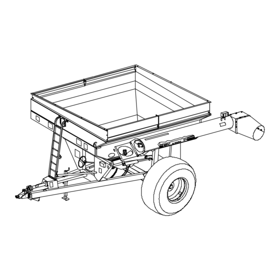
- Page 1 OPERATOR'S MANUAL PARTS CATALOG MODELS 674 & 672 Corner Auger GRAIN CART Model 674 Beginning With Serial Number B1651100 Model 672 Beginning With Serial Number B1649100 250915H Manufactured At: ® Unverferth Manufacturing Co., Inc. 27612 Temple Ave. Shell Rock, IA...
-
Page 2: Table Of Contents
TABLE OF CONTENTS SECTION II - PARTS SECTION I - OPERATION PAGE PAGE PTO ASSEMBLY ........2-2 INTRODUCTION ........1-3 PTO CLUTCH ........... 2-3 SAFETY ............ 1-4 SET UP FOR FIELD OPERATION ... 1-6 UNDERCARRIAGE ........2-4 AUGER ............. 2-6 PLASTIC HOSE PIPE INSTALLATION .. -
Page 3: Introduction
THANK YOU FOR YOUR PURCHASE! Please fill out and retain this portion for your records. For warranty consideration, please contact dealer where purchased. The serial number plate is located on the front side of your Corner Auger Grain Cart. Date of Purchase... -
Page 4: Safety
ACCIDENTS CAN BE PREVENTED WITH YOUR HELP! No accident-prevention program can be successful without the whole-hearted cooperation of the person who is directly responsible for the operation of the equipment. A large number of accidents can be prevented only by the operator anticipating •... - Page 5 NOTE! This SAFETY ALERT SYMBOL is found throughout this manual. It is used to call attention to instructions involving your personal safety and the safety of others. Failure to follow these instructions can result in INJURY OR DEATH. This symbol means ATTENTION! BECOME ALERT! YOUR SAFETY IS INVOLVED!
-
Page 6: Set Up For Field Operation
SET-UP FOR FIELD OPERATION Your grain cart comes set-up with exception of wheel/tire installation, side extensions, ladder, auger extension chute, electrical hook-up to tractor, and tire pressure check. If your implement dealer has not set up the preceding items, the procedure is simple. SIDE EXTENSION SET-UP Refer to parts page in Section 2 for extension placement. -
Page 7: Plastic Hose Pipe Installation
SET-UP DRIVELINE STORAGE Storage brackets are located on the inside right frame rail. Secure the PTO shaft to these brack- ets for extended transporting or seasonal storage. IMPORTANT: Remove and store the • complete PTO before towing grain cart behind a delivery truck. -
Page 8: Electrical Hook-Up
ELECTRICAL HOOK-UP Your Grain Cart is supplied with a seven-point SAE connector plug which will adapt to the receptacle found on several new tractors on the market today. If not available, an SAE J S60A seven-point outlet socket can be purchased from your Unverferth dealer (order Part #92824). -
Page 9: Dual Wheels
DUAL WHEELS SPINDLE 1. If necessary, replace existing wheel studs with longer 3/4-16 UNF x 3 1/2" studs. INSIDE DUAL WHEEL: 2. Install inside dual wheel. 3. Use 3/4-16 hex jam nuts (27/64" Thick) on small holes. 4. Tighten the five jam nuts to 200 Ft. Lbs. OUTSIDE DUAL WHEEL: 5. -
Page 10: Tractor Hook-Up
TRACTOR HOOK-UP Make sure sufficient counter-weight is used on the tractor's front-end. Move draw bar into closest position for even terrain. Make sure draw bar length and PTO telescoping limits are adequate for • uneven terrain, gullies, rice levees etc. Never exceed the maximum recommended hitch pin size which allows for uneven terrain. -
Page 11: Auger Fold Adjustment
AUGER FOLD ADJUSTMENT The auger fold linkage is adjusted at the factory and under normal operating conditions should not require adjustment. Disassembly for service or slight wear in the linkage pins may necessitate the need for adjustment. The 1/8" compression dimension is necessary for a good seal at the auger flanges and snap locking at the end of the cylinder stroke. -
Page 12: Hydraulic Auger Operation
HYDRAULIC AUGER OPERATION For PTO & DIRECT DRIVE Applications Initial start-up: Flow Door is to be closed. With flow door closed, engage hydraulic motor with maximum oil flow from tractor. NOTE: Free running auger oil pressure will range 500 PSI or less. The pressure gauge will register system work load as flow door is opened. -
Page 13: Adjustable Unloading Chute
ADJUSTABLE UNLOADING CHUTE (OPTIONAL) INSTALLATION: 250957 1. Remove existing chute. 2. Fold overlap and snap four end snaps. 3. Slide chute over outlet shroud with overlap towards hitch. 4. Install top and bottom strips over chute and fasten with existing capscrews, flatwashers and locknuts. -
Page 14: Seasonal Storage
250922A 8 hrs 20 hrs 250950 SEASONAL STORAGE Fully open flow door to retract and protect Flow Door Cylinder rod. Apply thin coating of General Purpose grease or spray equivalent to Auger Cylinder rod (extended in folded rest position). • 05-09-97 1-14... -
Page 15: Service Tips
LUBRICATION AND MAINTENANCE To keep your grain cart in top operating condition and to assure its proper performance and reliability for a long period of time, a periodic inspection and lubrication is a must. The lubrication locations and recommended schedule are as follows: A. -
Page 16: Adjustable Axle
ADJUSTABLE AXLE - MODELS 672, 674 ADJUSTABLE AXLE (120" - 154") Raise center axle weldment. Loosen clamp plate capscrews on slotted slides of axle weldment Extend axle to desired width and align holes for studs if greater than 144". Remove axle stud and spacer pipe from storage brackets on rear of axle. Install in outer set of holes for desired axle width. -
Page 17: Pto
PTO SHAFT & CLUTCH To avoid injury do not clean, adjust, unclog, or This Safety Alert Symbol means Attention! service PTO driven equipment when the tractor en- Become Alert! Your safety is involved! gine is running. Never exceed the recommended operating speed for the particular equipment in use. -
Page 18: Lubrication
D. Lubrication (Figs. D1 - D6) Lubricate with quality grease before starting work and every 8 operating hours. Clean and grease PTO drive shaft before each prolonged period of non-use. Molded nipples on the shield near each shield bearing are intended as grease fittings and should be lubricated every 8 hours of operation! Telescoping members must have lubrication to operate successfully regardless of whether a grease fitting is provided for that purpose! Telescoping members... -
Page 19: Chains
G. Chains (Figs. G1 - G3) NOTE: The chain is intended to prevent the shield from rotating against non-moving parts and thereby preventing shield damage. A properly installed chain will increase the service life of the shield. 1. Chains must be fitted so as to allow sufficient articulation of the shaft in all working positions. -
Page 20: Cone
K. To assemble guard: (Figs. K1 - K5) 1. Grease yoke groove and inner profile tube. 2. Fit bearing ring in groove with recesses facing profile tube. 3. Slip on half-guard. 4. Turn cone until it engaes correctly. 5. Install locking screw. 250968K L. -
Page 21: Quick Disconnect
QUICK DISCONNECT PIN Quick-disconnect P i n Compression Spring Washer Using a drift punch and hammer, drive the pin towards the retaining washer to force the complete assembly out. Clear the edges of the retaining washer bore to accept the new one by removing the deformed metal from the last peening operation to hold the washer in place. -
Page 22: Clutch
CLUTCH DISASSEMBLY Tighten the four hex nuts (12) Use special tool 9002007 to bend Remove the thrust plate with uniformly until the clutch pack all four retaining lugs back on the Belleville springs to get at the edge of the clutch housing. and hub are loose. -
Page 23: Driveline Safety Precautions
DRIVELINE SAFETY PRECAUTIONS - DANGER ZONE - Attention! Become Alert! 250968A Read and understand the equipment Operator's Avoid excessively long hardware or exposed and manual. protruding parts which can snag and cause entanglement. Follow all safety messages in the Operator's Manual and safety signs on the equipment. - Page 24 TIRE REFERENCE FOR QUESTIONS REGARDING NEW TIRE WARRANTY PLEASE CONTACT YOUR LOCAL ORIGINAL EQUIPMENT TIRE DEALER USED TIRES CARRY NO WARRANTY FOLLOWING ARE PHONE NUMBERS AND WEBSITES FOR YOUR CONVENIENCE Firestone www.firestoneag.com Carlisle www.carlisletire.com 800-897-3364 Phone 800-260-7959 800-352-0075 Goodyear www.goodyear.com 1-800-GOODYEAR Trelleborg www.trelleborg.com...
-
Page 25: Section Ii - Parts
SECTION II - PARTS PAGE PTO ASSEMBLY ........2-2 PTO CLUTCH ........... 2-3 UNDERCARRIAGE ........2-4 AUGER ............. 2-6 BOX & ELECTRICAL........ 2-8 DECALS ..........2-10 SIDE BOARDS ........2-11 LOWER AUGER AND DRIVELINE ..2-12 DRIVE LINE U-JOINT ASSEMBLY ..2-13 HUB ............ -
Page 26: Pto Assembly
PTO ASSEMBLY ITEM DESCRIPTION PART NO. PART NO. QTY NOTES PTO Shaft w/Shielding 94866 94868 1 3/4-20 Spline PTO Shaft w/Shielding 94867 95214 1 3/8-21 Spline Front Half PTO 94835 94841 1 3/4-20 Spline Front Half PTO 94826 95215 1 3/8-21 Spline Rear Half PTO 94827 94842... -
Page 27: Pto Clutch
PTO CLUTCH ITEM DESCRIPTION PART NO. PART NO. QTY, NOTES Clutch Complete 92925 94838 Items 7 Thru 17 Nut, M8 DIN 6330 Hex 92386 > • Belleville Spring (Red dot) 93815 > Repl. 92915 (White dot) Thrust Plate 92384 > Drive Plate 92850 >... - Page 28 PAINT GALLON SPRAY Black 9000913 9000533 Green 9002594 9001791 9002593 9002197 265915 Primer, Gray 9000914 9000592 Primer, White 9002595 Graphite 95201 250936 ITEM DESCRIPTION PART NO. QTY. NOTES Scale Hitch Bushing 250487B Scale Unit Only Capscrew, 1-8 UNC x 6 9390-195 Bushing to Frame Tube Lockwasher, 1"...
-
Page 29: Undercarriage
MODEL 672 & 674 - UNDERCARRIAGE ITEM DESCRIPTION PART NO. QTY. NOTES Page 2-2 Jack Assembly, Flange Mount 232311 Incl. 250022 & Fasteners Capscrew, 5/8 UNC x 1-3/4 9390-123 Lockwasher, 5/8 9404-029 Nut, 5/8 UNC Hex 9394-014 Jack, Swivel Mount - Top Wind 9003299 Repl. - Page 30 250937 • 06-30-00...
-
Page 31: Auger
MODEL 672 & 674 - AUGER ITEM DESCRIPTION PART NO. PART NO. QTY. NOTES Upper Auger 250416 265130 Upper Auger Housing 250652* 250013* × ×Includes Items 4 & 5A Flange Bearing, 1-1/2 4-Hole 92406 > Washer 9001197 > 2 x 1.554 x .134 Capscrew, 1/2-13 UNC x 5-1/2 9390-114 >... - Page 32 Electrical System Items 13 Thru 21 Serial #B19380099 & Lower Begin Serial No. B19380100 See Page 2-23 250938 • 12-19-01...
-
Page 33: Box & Electrical
MODEL 672 & 674 - BOX & ELECTRICAL ITEM DESCRIPTION PART NO. QTY. NOTES Window 92403 Kit 220512 Incl. Items 1-3 Window Molding 250431 • Bracket, Window Retaining 250461B Capscrew, 1/4-20 UNC x 1 9390-005 Locknut, 1/4-20 UNC 9936 • Ladder 250473B Tube, Manual... -
Page 34: Decals
MODEL 672 & 674 - DECALS ITEM DESCRIPTION PART NO. QTY. NOTES Decal, Brent By Unverferth 92553 Decal, Brent 9004234 • Prior to Serial #B21780100 Decal, Stripes Tricolored 92555 • Decal, Brent Fading Stripe 9004214 Prior to Serial #B21780100 •... -
Page 35: Side Boards
MODEL 672 & 674 - SIDE BOARDS ITEM DESCRIPTION PART NO. QTY. NOTES Serial #B1649100 Beginning Serial Thru #B18260999 #B18590100 Front Board 200215B 250870B 18" to 5" Tall Rear Board 200216B 250871B 18" to 5" Tall Left Front Side Board 250453B 250874B 18"... -
Page 36: Lower Auger And Driveline
LOWER AUGER AND DRIVELINE ITEM DESCRIPTION PART NO. PART NO. QTY. NOTES Drive Dog/Missle Shaft 250424 265125 4-Tooth 3-Tooth Hanger Bushing Assembly 250119 265132 2" I.D. Bushing, 2" / 2 1/2" I.D. 95315 9001198 Zerk, 90 9000875 > Capscrew, 3/8 UNC x 1-1/4 9390-056 >... -
Page 37: Drive Line U-Joint Assembly
DRIVE LINE U-JOINT ASSEMBLY ITEM DESCRIPTION PART NO. PART NO. QTY NOTES Complete U-Joint Ass'y 92911 95012 Yoke 92910 95010 Grease Zerk, 1/4-28 UNF 91160 > Yoke, 1-3/8-6 Spline 92909 95011 Quick-Disconnect Pin Kit 92362 > Cross & Bearing Kit 92364 93857 Grease Zerk... -
Page 38: Hub
MODELS 672 & 674 HUB ITEM DESCRIPTION PART NO. QTY. NOTES Spindle 2 7/8" 4 1/2" 3 3/4" 3 3/4" Bolt Circle 11.25" 13.187" 13.187" 13.187" Singles Duals Duals Serial No. & Lower Std, Scale Standard Scale 674 #B1651099 / 672 #B1649099 Singles Duals Beginning Ser. - Page 39 MODELS 672 & 674 - HUB - DUAL WHEELS Begin Ser. No. B19380100 ITEM DESCRIPTION PART NO. QTY. NOTES Hub Assembly 266456* Includes Items 1 thru 8 --3 3/4" Spindle Seal 92565 Ref. No. SA370605 Outer Cup 92462 HM212011 Outer Bearing Cone 92464 HM212049 Hub Cap...
-
Page 40: Adjustable Axle
MODEL 672 & 674 ADJUSTABLE AXLE - 120"-150" Trussed Style - For Replacement Only ITEM DESCRIPTION PART NO. QTY. 674 S/N B1651099 Beginning S/N & 672 - S/N B1649099 674 - B1651100 & 672 - B1649100 & Lower - 4 1/2" Spindles - - 3 3/4"... - Page 41 MODEL 672 & 674 ADJUSTABLE AXLE - 120" - 154" ITEM DESCRIPTION PART NO. QTY. NOTES Adjustable Axle Assembly 250641* Includes 1-9 & 21-23 - Option Adjustable Axle Assembly 250640 Includes Items 1 thru 9 Axle Weldment 265627 • RH Axle End 250670 LH Axle End 250670...
-
Page 42: Gear Box
GEAR BOX ITEM DESCRIPTION PART NO. QTY. NOTES Gear Box, Complete 9002812 Incl. Items 1-17 (Repl. 9000918) Shaft, Input 9001131 1.8:1 Gear Shaft, Output 9001132 1.8:1 Gear Bearing Cone 92697 Large Bearing Cup 92698 Large Bearing Cone 9001133 Bearing Cup 9001134 Bearing Cone 9001135... -
Page 43: 36" Flow Control Door Cylinder
MODEL 672 & 674 AUGER CYLINDER ITEM DESCRIPTION PART NO. PART NO. QTY. NOTES 2 1/2 x 14" 3 x 14" Cylinder, Complete 9001091 94778 9001125 94881 Seal Kit 9001126 94879 250911 FLOW CONTROL DOOR CYLINDER ITEM DESCRIPTION PART NO. QTY. - Page 44 233214D • 07-14-98 2-20...
-
Page 45: Hydraulic Pto Drive (Optional)
HYDRAULIC PTO DRIVE ITEM DESCRIPTION PART NO. PART NO. QTY. NOTES Hydraulic Drive Assembly 250086 250087 Includes 1 thru 24 Hydraulic Motor, 15.9 in. 9000744 9000744 • Repl. 9000750-9.99 in. Mounting Plate Weldment 230028 > Capscrew, 1/2UNC x 10 Hex 9390-436 >... -
Page 46: Scale (Optional)
MODEL 672 & 674 - SCALE UNIT ITEM DESCRIPTION PART NO. QTY. NOTES Single Dual Dual Hubs - B.C. 11 1/4" 13 3/16" 13 3/16" Spindle Dia. 2 7/8" 3.730" 3.750" 674 S/N B1582100 674 Beginning With S/N B165i100 Thru B165i099 672 Beginning With 672 S/N B1581100 Thru B1649099... -
Page 47: Scale (Optional)
MODEL 674 - ELECTRICAL BEGIN SERIAL #B19380100 ITEM DESCRIPTION PART NO. QTY. NOTES Wiring Harness, Front 9003509 Wiring Harness, Rear 9003510 Wiring Harness - Auger 9000375 Electrical Coupler 92450 Auger Light 9001155 • Connector, Male 9001660 • Not Applicable Light, Red - Tail/Turn 9003136 Light, Amber - Turn/Flasher 9003048... -
Page 48: Hydraulic Drive Kit (Optional)
HYDRAULIC DRIVE KIT (OPTIONAL) 280911 • ITEM DESCRIPTION QTY. NOTES PART NO. Hydraulic Drive Kit 280102 Hydraulic Motor 9004283 Hose, 3/4" I.D. x 88" 9004295 Hose, 3/4" I.D. x 88" 90° 9004296 9004285 Run Boss Tee 9001039 Pressure Gauge 9004304 Elbow, 1/4 Male x 1/4 Female 280066B Mount Weldment, Motor... -
Page 49: Section Iii - Scale
SECTION III - SCALE SCALE KIT LAYOUT & INSTALLATION ........... 3-2 SCALE MODEL 150 OPERATION ..................3-4 INSTALLATION REQUIREMENTS ............3-6 SHORT-FORM SET-UP/CALIBRATION ........... 3-7 CHANGE LBS TO KGS ................. 3-9 CHANGE UPPER RANGE ..............3-10 DOWNLOADER MODULE ..............3-11 TROUBLESHOOTING GUIDE ............... -
Page 50: Scale Kit Layout & Installation
SCALE KIT LAYOUT 250917 • 04-16-01... - Page 51 INSTALLATION OF SCALE KIT FOR MODELS 672 & 674 HITCH ASSEMBLY SPINDLE ASSEMBLY Remove the four 3/4 x 2 1/2" bolts With the cart empty, use a 5-ton jack and jack stands to support the weight (9390-146) and lockwashers (9404- of your grain cart.
- Page 52 Turn ON the scale: To Zero / Balance the Scale 1. Press [ON]. 1. Press the [NET/GROSS] key and within three seconds, 2. Press the [ Z ERO] key. HELLO ZERO 250955 A brief message is displayed (such as "HELLO"). The scale enters GROSS weighing mode.
- Page 53 To Select Gross Mode: 2. If Gross mode, press GROSS mode displays the weight [NET / GROSS]. change since the unit was last ZERO/ BALANCED. The [NET / GROSS] key is an alternat- ing action key. If the scale is in the 1.
-
Page 54: Operation
SCALE BOTTOM PANEL OPERATION: • CABLE CONNECTIONS: It is recommended that the indicator reads 0000 by pressing TARE before unload- ing the cart in a truck or wagon. Once the cart is finished unloading, the exact (negative) amount of grain unloaded is displayed. -
Page 55: Short-Form Set-Up/Calibration
"Short Form" Setup & Calibration: WARNING! THIS INDICATOR WAS CALIBRATED AT THE FACTORY TO WEIGH ACCURATELY WITH YOUR SYSTEM. ADDITIONAL CALIBRATION IS NOT NECESSARY UNDER NORMAL CONDITIONS. The Short Form Setup & Calibration procedure allows It is important to use an average of several weights before you to change the "SETUP"... - Page 56 NOTE: Press the [ZERO] key for additional help information during Setup and Calibration. Step 1) Press the [NET/GROSS] key to cause the 1: Connecting EZ Indicator to Other Load Cells: "flashing" digit to count upward. You will need the number and type of loadcells used in the new scale system.
- Page 57 To change scale from lbs to kgs: 4. Press the [NET/GROSS] key to increment the "flashing" digit. 1. Press [ O N] to turn on the scale. Change the 1 to 5. 2. To enter Short Form Calibration & Setup press and hold the [ZERO] key, then press the [ON] key and hold them both together until the indicator displays "setup", then let...
- Page 58 To change scale upper range: 4. Press the [NET/GROSS] key to increment the "flashing" digit. 1. Press [ O N] to turn on the scale. Change the 6 to 7 (700000#) or desired higher number. 2. To enter Setup press and hold the [ZERO] key, then press the [ON] key and hold them both together until the indicator displays "setup",...
- Page 59 DOWNLOADER MODULE (Optional) Quick Guide Suggestion: You may want to manually keep a log of dates and times at various farms and fields to check and identify the scale indicator data. 1. Plug the Memory Converter into the bottom of the scale indicator and the downloader Module into the Memory Converter.
- Page 60 Digi-Star Scale - Troubleshooting Guide Does the indicator turn on? Check for 12VDC at the junction between the AC/DC converter power cord. If you do not have a multimeter, use a car battery to power Does the indicator respond the scale. If the indicator still does not come on, when you step on the scale? send it in for repair.
- Page 61 Ø Record exactly what you take out of storage and haul to the elevator. Scales can be easily installed to your Brent grain cart at any time without any modification. The scale investment increases the grain cart's trade-in value, so the investment in the scale option is quickly returned.
- Page 62 NOTES 3-14...
-
Page 63: Section Iv - Tarp
SECTION IV - TARP Tarp Parts ............4-2 674 S/N B1651100 Thru B18260999 672 S/N B1649100 Thru B17480999 Tarp Installation ..........4-4 674 S/N B1651100 Thru B18260999 672 S/N B1649100 Thru B17480999 Tarp Parts 674 Beginning S/N B18590100 ..... 4-8 Tarp Installation 674 Beginning S/N B18590100 ... - Page 64 250932 • 11-13-97...
- Page 65 MODELS 672 & 674 - TARP ITEM DESCRIPTION PART NO. QTY. NOTES Tarp Kit w/End Caps 250320 Includes Items 1 Thru 41 Tarp Package 9001505 Includes Items 1 thru 37 Capscrew, 1/2-13 x 1 Flange 9001529 Capscrew, 3/8-16 x 1 3/4 9001530 Eyebolt 9001531...
-
Page 66: Tarp Installation
TARP INSTALLATION 250933 Fig. 1 Install side board extensions to box. NOTE: Use a center punch to remove knock- See page 1-6. outs from side boards. Punch out a set of knockouts for each bow. Assemble end caps (38) to front and rear side boards. - Page 67 Install rod eye (3), nut (5), and locknut (6) at front of latch plate (32) approxi- mately 3/4" from end. See Fig. 4. Fig. 6 270917-6 Table 1 OVERALL LENGTH Fig. 4 270917-4 Model Fixed Tube Ridge Pole RollingTube "L" 672,674 160"...
- Page 68 11. Assemble pvc pipes (18,19) and con- 14. Assemble tarp (37) and stops with nectors (20) as required with plastic caps, (28,29) to top of left hand side adhesive (22). See Fig. 8. boards with capscrews and nuts (40). Note: With tension on tarp, install 12.
- Page 69 16. Install crank standoff (15) to wagon or 17. Unroll tarp and let hang over edge of cart. OPTIONAL: Install crank stand- box. Pull stretch rope until all slack off with U-bolts to rear ladder. has been removed from the roll re- turn assembly.
- Page 70 MODELS 672 & 674 - TARP 234913 • 04-01-02...
- Page 71 MODELS 672 & 674 - TARP ITEM DESCRIPTION PART NO. QTY. NOTES Tarp Kit w/End Caps 250399 Includes Items 1 Thru 35 Tarp Ratchet / Ridge Strap 9003098 Repl. 105819 Nylon Spool, Front (Red) 9003549 • Repl. 105825 • Tarp Spring, Front (Red) 105826 Crank, Roll-Over Tarp 9003140...
- Page 72 TARP INSTALLATION Fig. 1 251916 Install the side board extensions to Insert the bows (23) into the slots in the box. See page 1-6. the left side board. Retain with 3/8 x 1" flange screw (29) and flange Assemble the end caps (24) to the nut (30).
- Page 73 Insert the small 1" tube by sliding it Attach the hooks on each end of the into the small pocket of the tarp. Align two ridge strap assemblies to the holes the holes at one end and fasten with in the center of the end caps. Run the a rivet.
- Page 74 ATTACHING SPOOLS TO ROLL TUBE REAR SPOOL (BLACK) To ensure the spring tab fully engages in the tube cartridge, turn The inside of the spools are pre-greased the spool COUNTERCLOCKWISE for use and color coded for assembly. about one inch and push. To fasten the spool to the cartridge tube, slide Slide the rubber ring on the roll tube the PVC spacer until holes align, then...
- Page 75 ATTACHING CABLES AND RATCHETS WRAPPING CABLE 12. With the tarp hand rolled to the cov- ered position, attach the barrel end of the cable to the barrel groove on the spool. 13. Now wrap the cable around the spool. Be sure the cable follows the grooves while doing so.
- Page 76 HAND CRANK HANDLE INSTALL FLEX DRIVE 15. With both ratchets firmly mounted to the side of the box, remove the finger tight nut and bolt that holds the PVC spacer on at the rear (red) end of the roll tube. Holding the flex drive end of the handle parallel to the roll tube, slide the shaft into the end of the tube protruding from the spool and...
- Page 77 TARP OPERATING SAFETY INFORMATION n n n n n n Always use adequate caution when operating tarp. Make sure tarp is open before unloading or loading. Make sure nobody is on or near the tarping system before and during operating. Do not operate tarp with box hoisted in an elevated position.
- Page 78 TARP TROUBLE SHOOTING GUIDE PROBLEM SOLUTION CABLES DO NOT STAY IN GROOVES ON 1. Cable ratchets may need offset NYLON SPOOLS WHEN OPERATING. adjustment. 2. Cable tension may need adjustment. 3. Spools may be binding on roll tube, need cleaning and regreasing. TARP DOES NOT WIND SMOOTH.
- Page 79 NOTES 4-17...
- Page 80 MEMBER FEMA FARM EQUIPMENT MANUFACTURERS A S S O C I A T I O N TCMANUALS\PM5\250475-092995-1\REV092203\122904-2...
Need help?
Do you have a question about the Corner Auger and is the answer not in the manual?
Questions and answers