OHAUS Explorer Service Manual
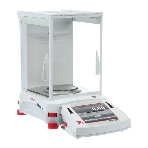
Semi-micro balances
Hide thumbs
Also See for Explorer:
- Service manual (114 pages) ,
- Instruction manual (52 pages) ,
- Installation instructions manual (8 pages)

Related Manuals for OHAUS Explorer


Summary of Contents for OHAUS Explorer
- Page 1 ® Explorer Semi-Micro Balances Service Manual Ohaus Corporation www.ohaus.com Explorer 5 Semi-Micro Balances...
-
Page 2: Table Of Contents
2.2 SOFTWARE 2.3 DIAGNOSTIC GUIDE 3 MAINTENANCE / REPAIR PROCEDURES 3.1 PREVENTIVE MAINTENANCE 3.2 OPENING THE BALANCE 3.2.1 Preparation for Opening Explorer Models ® 3.2.2 Opening the Terminal Module 3.2.3 Opening the Base Module with a Draftshield 3.3 REPLACING THE LOAD CELL 3.4 REPLACING THE PRINTED CIRCUIT BOARD ASSEMBLIES (PCBA) - Page 3 4.4.4 Off-Center Load Test 5 PARTS LISTS & DIAGRAMS 5.1 TERMINAL SPARE PARTS 5.2 BASE SPARE PARTS EXPLOERER 5 DECIMAL 5.3 DRAFTSHEILD SPARE PARTS EXPLORER 5 DECIMAL APPENDIX A - USER CALIBRATIONS A.1 SPAN CALIBRATION A.2 LINEARITY CALIBRATION A.3 TOUCH SCREEN CALIBRATION APPENDIX B - DIAGNOSTIC / SERVICE MENU B.1 User Accessible Diagnostics...
- Page 4 4-4 Off Center Load Mass Values ........................41 4-5 Tolerance Table ……………………………………………………………………………………………………42 5-1 Terminal Spare Parts ..........................43 5-2 Base Spare parts Explorer 5 Decimal Models………………………………………………………………….45 5-3 Draft Shield Spare Parts Explorer 5 Decimal Models………………………………………………………….47 B-1 Service Calibration Mass Values ......................…54 C-1 Interface Command List ...........................56...
-
Page 5: Getting Started
Chapter 4 - Testing Contains a list of required test masses, an operational test, segment display test, performance tests and adjustments. Chapter 5 - Drawings and Parts Lists Contains exploded views of Explorer balances ® identifying all serviceable components. Appendix A - User Calibrations... -
Page 6: Tools And Test Equipment Required
TOOLS AND TEST EQUIPMENT REQUIRED Common hand tools are sufficient to disassemble the Explorer balances. ® A PC running Microsoft Windows XP or later. Explorer Software Service Tool, PN 83032124 ® RS232 Cable – Balance to PC PN 80500525 Digital voltmeter (DVM) with an input impedance of at least 10 meg-ohms at 1 volt DC. -
Page 7: Unit Capacity And Readability
26.03985 0.00005 0.000005 0.00005 0.00005 0.000005 0.000005 7.9156 7.91557 14.5119 14.5119 3.43008 7.91557 baht 0.00001 0.000001 0.00001 0.00001 0.000001 0.000001 10.2882 10.28824 18.8618 18.8618 4.45824 10.28824 tola 0.00001 0.000001 0.00001 0.00001 0.000001 0.000001 Ohaus Corporation www.ohaus.com Explorer 5 Semi-Micro Balances... -
Page 8: Balance Operation
BALANCE OPERATION ® ® The Explorer is a very simple to use yet sophisticated balance. Please refer to the Explorer Instruction Manual for complete information on the set up and use of the balance. Overview of the Controls. 1.6.1 This equipment utilizes a touch-sensitive display. -
Page 9: Menu Navigation
1.6.3 Menu Navigation. All menu navigation is performed by touching the display. To enter the Menu, touch from Menu any Application Home screen. The Main menu appears, with buttons for Main, Back Done Ohaus Corporation www.ohaus.com Explorer 5 Semi-Micro Balances... -
Page 10: Changing Settings
Application. Home at any time the & buttons can be touched to navigate to the desired area of Note: Main Back Done the menu or return to the current Application. Ohaus Corporation www.ohaus.com Explorer 5 Semi-Micro Balances... -
Page 11: Functions And Icons
Zero within the tolerances set in the AZT menu (see Balance Settings). 1.6.5.4 TouchLess Sensor Status Explorer Semi-Mirco Balances have four TouchLess sensors that can be assigned a unique function when activated (e.g., zero, print, tare, Automatic draftshield door etc). - Page 12 Perform a numeric operation using the keypad. Press = to view the result. To Clear the display: Press CE to clear the entry, C to clear all Touch to close and return to the current Application. Ohaus Corporation www.ohaus.com Explorer 5 Semi-Micro Balances...
-
Page 13: Legal For Trade (Lft)
When Legal for Trade is set to ON, the menu settings are affected as follows: Calibration Menu AutoCal internal Calibration, Automatic Calibration, and Calibration Test All other functions are hidden. Balance Setup Menu Ohaus Corporation www.ohaus.com Explorer 5 Semi-Micro Balances... -
Page 14: Menu Structure
Display Touch Panel. By touching an item on the display a further set of options will appear. 1.9.1 User Menu ® For more detail on using the menu, see the Explorer Instruction Manual. ® TABLE 1-4 EXPLORER... -
Page 15: Diagnostics Menu
Note: This switch is also used in conjunction with the Legal for Trade menu item. When the Legal for Trade menu is set to ON, the switch must be set to the ON position to prevent calibration and changes to metrologically significant settings. Explorer Switch Ohaus Corporation www.ohaus.com Explorer 5 Semi-Micro Balances... -
Page 16: Diagnostic Guide
See Appendix C for the software upgrade procedure. Check the Service Bulletins on the Ohaus DMX site for information on software upgrades. 2.3 DIAGNOSTIC GUIDE Diagnostic Guide designed to help locate the problem area quickly and easily. The probable causes are listed with the most common cause first. -
Page 17: Diagnostic Guide
NOTE: If more than one symptom is observed, approach one area at a time, and remember that the symptoms may be interrelated. If a problem arises that is not covered in this manual, contact Ohaus Corporation for further information. TABLE 2-1 DIAGNOSTIC GUIDE... - Page 18 Install pan and re-zero. zero range IDNR error Type data error Contact the authorized dealer --operation not There is no sample on the pan when Place sample on the pan and redo Tare allowed-- doing Tare Ohaus Corporation www.ohaus.com Explorer 5 Semi-Micro Balances...
- Page 19 Base Main PCBA, see 3.4.2 and date. Note: There is 40-second timeout control for print under stable requirement. If the unstable condition continues over 40 seconds, balance will send “ES” to the printer. Ohaus Corporation www.ohaus.com Explorer 5 Semi-Micro Balances...
-
Page 20: Maintenance / Repair Procedures
3 MAINTENANCE / REPAIR PROCEDURES PREVENTIVE MAINTENANCE Ohaus balances are precision instruments and should be carefully handled, stored in a clean, dry, dust-free area, and cleaned periodically. Follow these precautionary steps: *When a balance has had chemicals or liquids spilled on it, all exterior surfaces should be cleaned as soon as possible with warm water on a damp cloth. - Page 21 Note: If the sliding doors and top lid have been installed, first open the sliding glass doors on both sides and open the top lid to make space for the glass shelf. Draftshield removal – removes the Top and Side Doors and the Front Panel Remove the Platform and Wind Ring as required. Ohaus Corporation www.ohaus.com Explorer 5 Semi-Micro Balances...
-
Page 22: Opening The Terminal Module
1. Remove the Terminal Bracket from the Terminal Module. Press the two Angular Adjust Buttons to allow the Terminal Bracket to swing free. Flex the bracket it at its center to release one hinge pivot at a time. Ohaus Corporation www.ohaus.com Explorer 5 Semi-Micro Balances... - Page 23 4. Disconnect the ribbon cable connecting the two assemblies. Using a finger nail or a thin screw driver blade rotate the black cable-lock on the connector 90° so that it is perpendicular to the cable. Ohaus Corporation www.ohaus.com Explorer 5 Semi-Micro Balances...
-
Page 24: Opening The Base Module With A Draftshield
3.2.3 Opening the Base Module with a Draftshield Prepare the balance as instructed (3.2.1) Remove the EMC plate from the Base. Remove the back plate. 4. Disconnect the Light Cable. Ohaus Corporation www.ohaus.com Explorer 5 Semi-Micro Balances... - Page 25 8. Turn the Module over. Remove the Top Housing being careful to route the Light Cable and Motor Cables (if equipped) through the holes in the Upper Housing. 9. Disconnect the Bubble Light Cable from the Connect PCBA. Ohaus Corporation www.ohaus.com Explorer 5 Semi-Micro Balances...
-
Page 26: Replacing The Load Cell
2. Remove the Load-cell Shield by lifting vertically. 3. At this point it is important to take note the routing of the cable from load cell PCBA and InCal mechanism to balance main PCBA. Ohaus Corporation www.ohaus.com Explorer 5 Semi-Micro Balances... - Page 27 Take special care to route the wires and cables. Proper routing is important for RFI/ESD performance. Ensure that the wires or cables are not pinched during reassembly. Also take note of the clip holding the cable ti the base. Ohaus Corporation www.ohaus.com Explorer 5 Semi-Micro Balances...
- Page 28 Location and routing of the cables from load cell to main PCBA: 6. See Appendix C for instructions on how to use the software Service Tool to configure the new load-cell to the balance. Ohaus Corporation www.ohaus.com Explorer 5 Semi-Micro Balances...
-
Page 29: Replacing The Printed Circuit Board Assemblies (Pcba)
• Slide out the module. 3. Remove the Interconnect terminal PCB by removing the two screws as shown below. 4. Remove the 4 screws holding the terminal PCBA from the terminal housing as shown below. Ohaus Corporation www.ohaus.com Explorer 5 Semi-Micro Balances... - Page 30 • Unlock the LCD ribbon cable connector (see “Opening the Terminal Module” above), removing the cable. • Disconnect the Touch Panel flex cable by sliding the black release. Remove the cable from the connector. • Remove the 4 mounting screws and lift out the Terminal Main PCBA. Ohaus Corporation www.ohaus.com Explorer 5 Semi-Micro Balances...
- Page 31 Remove the LC Display by simply lifting it out. 8. See Section 3.7 for instructions on changing the Touch Panel. Ohaus Corporation www.ohaus.com Explorer 5 Semi-Micro Balances...
-
Page 32: Base
• Loosen the 2 retaining screws approximately 2 turns • Rotate the retaining washers so that it no longer engages the PCB, slide out the PCBA • Disconnect the cable at the Connect PCBA. Ohaus Corporation www.ohaus.com Explorer 5 Semi-Micro Balances... - Page 33 • During disassembly and re-assembly note how the switch engages the Switch Actuator. 4. Remove Main PCB • Remove the left IR Sensor PCBA (see above). • Disconnect the cables along the top edge of the PCB. Ohaus Corporation www.ohaus.com Explorer 5 Semi-Micro Balances...
-
Page 34: Replacing The Function Label
Peal off the remaining liner and press the surface starting at the attached area and working outward to avoid bubbles under the label. Ohaus Corporation www.ohaus.com Explorer 5 Semi-Micro Balances... -
Page 35: Replacing The Touch Panel
The bearing assembly is made of three parts, two disks with a bearing ring in the center. The curved surface of the dicks should face the ball bearings. Assemble the foot components in the order shown in the sketch below. Ohaus Corporation www.ohaus.com Explorer 5 Semi-Micro Balances... -
Page 36: Replacing The Ionizer
Replacing the Ionizer. 1. Opening the Balance back plate referring to 3.2.3. 2. Locate and remove the cable from the Ionizer to Motordriver Board. 3. Remove the 3 mounting screws holding the Ionizer in place. Ohaus Corporation www.ohaus.com Explorer 5 Semi-Micro Balances... -
Page 37: Replacing The Auto Door Mechanism
PCBA makes sure the PCBA sits firmly in place before tighten the screw, there will be two bracket on the left and right and one in the center to hold the PCBA in place. Ohaus Corporation www.ohaus.com Explorer 5 Semi-Micro Balances... -
Page 38: Replacing Bracket Driver Assembly
Note: At this point take note because when you removing the bracket at the same time you are removing the belt. DO NOT STREACH the belt when removing from the assembly and replace it if is damage or broken. Ohaus Corporation www.ohaus.com Explorer 5 Semi-Micro Balances... -
Page 39: Assemble Motor Driver Assembly
1. Install the assembly by making sure the driver assembly sits frimly in place before screwing the 4 scerews securring the assembly in place. 3.9.4 Replacing the motor. 1. Remove the 4 screws holding the motor to the motor bracket and isolate the bracket from the motor. Ohaus Corporation www.ohaus.com Explorer 5 Semi-Micro Balances... -
Page 40: Testing
TEST MASSES REQUIRED ® The masses required to test the Ohaus Explorer Semi Micro Balance must meet the requirements of the ASTM or OIML Tolerances listed in the table. Poor quality calibration masses be the can cause of frustrating diagnostics. -
Page 41: Precision Test
Set the Stability setting to 4d (its lowest setting). Set the Filter level to “Middle”. Set the AZT (Auto Zero Tracking) to 3d (its lowest setting). Do not turn it off. Ohaus Corporation www.ohaus.com Explorer 5 Semi-Micro Balances... - Page 42 Calculate the Delta x Delta for each reading and record in worksheet. Add the ten Delta x Delta values and divide by 9 Calculate the Standard Deviation by applying the square root of the result from step 8. Standard Deviation =___________ Ohaus Corporation www.ohaus.com Explorer 5 Semi-Micro Balances...
-
Page 43: Linearity Test
Pan. OCL test may also be referred to as an Eccentricity Test (OIML). The test weight used in this test 1/3 the capacity of the balance. See table for the test weight values. Ohaus Corporation www.ohaus.com Explorer 5 Semi-Micro Balances... - Page 44 Specifications Tables (Chapter 1). If this maximum is exceeded verify the test conditions and retest the balance. If there is no improvement the load-cell must be replaced. Note: In high resolution balances (Class I) it may be necessary to zero or tare between each location. Ohaus Corporation www.ohaus.com Explorer 5 Semi-Micro Balances...
- Page 45 ±0.24 ±0.19 (mg) Repeatability 20g (mg) ±0.015 ±0.015 ±0.015 ±0.015 ±0.015 Repeatability 100g ±0.035 ±0.035 ±0.035 ±0.035 ±0.035 (mg) ±0.15/5place ±0.15/5place ±0.15/5place Relative Linearity (mg) ±0.15 ±0.15 ±0.2/ 4place ±0.2/ 4place ±0.2/ 4place Ohaus Corporation www.ohaus.com Explorer 5 Semi-Micro Balances...
-
Page 46: Parts Lists & Diagrams
PARTS LISTS & DIAGRAMS ® This section of the manual contains parts lists and exploded views for the Explorer balances. These are designed to identify the parts which can be serviced on the balance in the field. The parts list and exploded views are separated into separate sections for the Terminal, the Base and the Draftshield. - Page 47 SP Bottom Housing Terminal 2.0 EX With Two USB Port Bracket Assembly, Terminal EX Cable Kit, Terminal EX Hardware Kit, Terminal EX Not shown Terminal, complete EX Not Shown Terminal, complete EX (V2.0) Ohaus Corporation www.ohaus.com Explorer 5 Semi-Micro Balances...
- Page 48 BASE SPARE PARTS EXPLORER 5 DECIMAL MODELS. Ohaus Corporation www.ohaus.com Explorer 5 Semi-Micro Balances...
- Page 49 TABLE 5-2 BASE SPARE PARTS EXPLORER 5 DECIMAL MODELS. Drawing Item Description SP Pan, 80mm EX SP BUFFER PAN EX SP EMC Plate 5PLACE EX SP Top Housing Ass. 5place EX SP IR Sensor PCBA EX SP Base EX SP Latch Assy, Front-glass EX...
- Page 50 DRAFTSHIELD SPARE PARTS EXPLORER 5 DECIMAL MODELS Ohaus Corporation www.ohaus.com Explorer 5 Semi-Micro Balances...
- Page 51 TABLE 5-3 DRAFT SHEILD SPARE PARTS EXPLORER 5 DECIMAL MODELS. Drawing Item Description SP Slide Door Top DS EX Top Cover Backwall EX Door Top DS EX SP PCBA Door Sensor EX Glass Assy – Right EX SP, Backwall Kit 5 Place, EX...
-
Page 52: Appendix A - User Calibrations
A.1 SPAN CALIBRATION ® The InCal system in Explorer balances with will perform a good span calibration as long as there is no damage to the load-cell. Verification with an external weight should be done if there is a question of the balances accuracy. -
Page 53: Linearity Calibration
With the balance turned ON, touch Menu then User Settings then Display Settings and then Touch Calibrate. Touch Calibrate: “Touch the screen at the center of the ring. O Press here.” (First top-left, then bottom-right) Ohaus Corporation www.ohaus.com Explorer 5 Semi-Micro Balances... -
Page 54: Appendix B - Diagnostic / Service Menu
If the wiring is okay verify that voltage (3.3 VDC) is reaching the Sensor PCBA, pins 2 and 4. Service Menu The Service Menu is intended for use by service personnel only. A password is required to access this menu, see the next section. Ohaus Corporation www.ohaus.com Explorer 5 Semi-Micro Balances... -
Page 55: Service Sub-Menu
The Service sub-menu, allows authorized service personnel to monitor Ramp or perform a variety of service weight calibrations. A password is required to access this menu. The current password is “Explorer” (SW: 1.10) and “OHAUS” (SW: 1.03). Software in the initial production units may not have all of the service items shown. Ohaus Corporation www.ohaus.com... - Page 56 Service Span calibration and then a Service Internal Calibration. The sequence of loading the test weights on the platform is very important to insure a correct linearity calibration. Refer to the diagram below for the correct weight sequence. Ohaus Corporation www.ohaus.com Explorer 5 Semi-Micro Balances...
- Page 57 SERVICE INTERNAL CALIBRATION The internal calibration weight is used to calibrate the balance. If a pan, pan support or load-cell is changed a Service Span Calibration or Service Internal Calibration should be done. Ohaus Corporation www.ohaus.com Explorer 5 Semi-Micro Balances...
-
Page 58: B-1 Service Calibration Mass Values
Balance Type, Max, d, Balance ID, IDNR, Loadcell Type, Loadcell Serial Number, Terminal Serial Number, Terminal SW Version, Base SW Version. Exit Service Mode Exits the Service Mode and returns to Normal Mode. Ohaus Corporation www.ohaus.com Explorer 5 Semi-Micro Balances... -
Page 59: Appendix C - Service Tool
The latest software service tool and support files are available on the Ohaus DMX site. Please read the Service Tool Instruction Manual (Part Number 30032352) which is also available on Ohaus DMX site. Ohaus Corporation www.ohaus.com... -
Page 60: Balance Commands
Print Serial Number. Print base software version, terminal software version and LFT ON (if LFT is set ON). Set Counting APW (x) in grams. (must have APW stored) Print Counting application APW. Ohaus Corporation www.ohaus.com Explorer 5 Semi-Micro Balances... - Page 61 0 = print unstable data, same as IP; 1 = print stable only , same as SP. 0 = disable response; 1 = enable response. Attention: this command only controls the “OK!” response. Ohaus Corporation www.ohaus.com Explorer 5 Semi-Micro Balances...
- Page 62 Percent Weighing Check Weighing Dynamic Weighing Filling Totalization Formulation Differential Peak Hold Density Determination Note 3: Unit list Index Unit Index Unit Custom unit 1 Custom unit 2 Custom unit 3 tical tola baht Ohaus Corporation www.ohaus.com Explorer 5 Semi-Micro Balances...
-
Page 63: Rs232 (Db9) Pin Connections
RS232 (DB9) Pin Connections USB Interface The Ohaus USB Interface is a unique solution to the problem of connecting a balance to a computer using a Universal Serial Bus (USB). USB devices are categorized into classes such as disk drives, digital cameras, printers, etc. - Page 64 3.3.3. When using the USB interface with programs that limit the number of COM port designations (e.g. Ohaus MassTracker allows only COM1, 2, 3, & 4), it may be necessary to assign one of these port numbers to the new virtual port. This can be...
-
Page 65: Appendix D - Firmware Upgrade Via Usb
APPENDIX D FIRMWARE UPGRADE VIA USB From version 2.00 the Explorer firmware can be upgraded via a USB flash drive. The whole process takes less than 10 minutes. Please follow below steps to upgrade the firmware using a USB flash drive. - Page 66 4. Press [Start] button to start the upgrade process. Note: Keep the USB flash drive connected and make sure the power is balance power is ON during the entire upgrade process. Ohaus Corporation www.ohaus.com Explorer 5 Semi-Micro Balances...
- Page 67 Ohaus Corporation www.ohaus.com Explorer 5 Semi-Micro Balances...
- Page 68 ™ Registered trademark of Ohaus Corporation. The information contained in this manual is believed to be accurate at the time of publication, but Ohaus Corporation assumes no liability arising from the use or misuse of this material. Reproduction of this material is strictly prohibited.
Need help?
Do you have a question about the Explorer and is the answer not in the manual?
Questions and answers